

How Much Ventilation Does a Generator Room Need? | PAVO
A generator room is not a store room with a machine in it. It is part of the cooling system, and the cooling system is sized in cubic metres per second, not in square metres of floor.
How much ventilation does a diesel generator room need? A 500 kVA set needs about 12 m³/s of air at full load — 9.2 m³/s by the 48.5 CFM-per-kW rule, 12.1 m³/s by heat balance — with about 4.8 m² of louvre free area at 2.5 m/s face velocity. Size the room on the larger figure.
Contents
- The Three Airflows a Generator Room Must Move
- The Arithmetic: Sizing Room Airflow for a 500 kVA Set
- From Airflow to Louvre: Free Area, Face Velocity and Static Pressure
- Radiant Heat: The Kilowatts the Radiator Never Sees
- Layout Rules That Decide Whether the Numbers Work
- Three Rooms That Got It Wrong
- Frequently Asked Questions
- Specification Checklist: Seven Numbers Before the Walls Go Up
The Three Airflows a Generator Room Must Move
A generator room moves three different airflows, and they are not interchangeable. Confusing them is the most common sizing error in the whole subject. A room that supplies enough combustion air can still cook the set, because combustion air is the smallest of the three. There is no warm-up period for the room either: the automatic transfer switch calls the set to full load within seconds of a grid failure, so the ventilation has to be ready before the outage, not after it.
Combustion Air
The engine burns fuel, and burning fuel needs oxygen. A 400 kW set at full load draws roughly 0.6–0.7 m³/s of combustion air — about 3.5 CFM per kW of output. That figure comes from the engine datasheet, and it is the only airflow the engine itself demands. It is also the figure most often quoted in isolation, which is how rooms end up with a louvre sized for combustion and nothing else.
Combustion air is roughly 5% of the total room airflow. A louvre sized on combustion air alone starves the radiator by a factor of twenty.
Radiator Cooling Air
The radiator is the largest consumer of air in the room. A skid-mounted radiator on a 500 kVA set moves 8–12 m³/s through its core at full load, depending on the fan and the core. That air enters through the intake louvre, crosses the room, passes through the radiator, and leaves through the discharge. It is the same air that cools the room. There is no separate “room cooling” system on a standard installation. The radiator fan is the room ventilation fan.
This is why the radiator datasheet, not the room volume, is the starting point for sizing. The fan moves a stated volume against a stated static pressure. The room has to pass that volume without adding more resistance than the fan can overcome.
The Air That Carries Radiant Heat Away
The third airflow carries the heat that never reaches the radiator: heat radiating off the engine block, the alternator, the turbocharger and the exhaust pipework. On a 400 kW set it is roughly 50–75 kW — small beside the radiator load, but it is the heat that sets the room temperature when the set is running at part load or when the radiator is ducted outside. A room with a remote radiator still needs ventilation for this heat. The radiator is outside; the engine is not.
The three airflows add. Room airflow equals radiator cooling air plus combustion air plus the air needed to carry radiant heat out at an acceptable temperature rise. In practice the radiator figure dominates, and the other two are added as margins. The arithmetic is in the next section.
The Arithmetic: Sizing Room Airflow for a 500 kVA Set
Two methods size room airflow. Both are used in practice, and they do not give the same answer. That is not a contradiction. One is a rule of thumb, the other is a heat balance, and the honest design uses the larger of the two.
The rule of thumb: cooling air is about 45 CFM per kW of output, and combustion air about 3.5 CFM per kW. Together, about 48.5 CFM per kW. For a 500 kVA set delivering 400 kW at 0.8 power factor, that is 400 × 48.5 = 19,400 CFM, or about 9.2 m³/s. The rule assumes a room temperature rise below 20°F (11°C) and a standard radiator. It is accurate enough for a preliminary layout and for checking a contractor’s figure.
The heat-balance method starts from the heat the room has to remove and the temperature rise the design will accept. The formula, in SI units:
Q (m³/min) = 53.5 × H ÷ ΔT + combustion air
where H is the heat rejected to the room in kW and ΔT is the allowable room temperature rise in °C. A published design-guide worked example for a 500 kW set takes H = 180 kW and ΔT = 11°C: (53.5 × 180) ÷ 11 = 876 m³/min of cooling air, plus 30 m³/min of combustion air, for a total of 906 m³/min — about 15.1 m³/s. At 2.5 m/s face velocity that needs 6.0 m² of louvre free area, or 12.0 m² of gross louvre at 50% free area.
Apply the same method to a 500 kVA set. Heat rejected to the room is roughly 36% of output, about 144 kW for a 400 kW set. (53.5 × 144) ÷ 11 = 700 m³/min, or 11.7 m³/s, plus 0.4 m³/s of combustion air: 12.1 m³/s total. The heat-balance figure is about 30% higher than the rule of thumb. Design to the heat-balance figure. The rule of thumb is a check, not a design basis.
| Set size | Output (0.8 pf) | Rule of thumb (48.5 CFM/kW) | Heat balance (ΔT 11°C) | Design airflow | Louvre free area at 2.5 m/s | Gross louvre at 50% free area |
|---|---|---|---|---|---|---|
| 250 kVA | 200 kW | 4.6 m³/s | 6.0 m³/s | 6.0 m³/s | 2.4 m² | 4.8 m² |
| 500 kVA | 400 kW | 9.2 m³/s | 12.1 m³/s | 12.1 m³/s | 4.8 m² | 9.7 m² |
| 1000 kVA | 800 kW | 18.3 m³/s | 24.1 m³/s | 24.1 m³/s | 9.6 m² | 19.3 m² |
Three things in that table deserve attention. First, the numbers are large. A 500 kVA set needs a louvre bank of nearly 10 m² gross — roughly a 5 m by 2 m opening. That is a wall, not a vent. Second, the airflow scales with output, not with room volume. A bigger room does not need less air; it needs the same air, and the air changes per hour simply fall. Third, the heat-balance column is consistently higher, because the rule of thumb was calibrated on cooler rooms. At 45°C ambient, the heat-balance figure is the one that keeps the set at rating.
Two adjustments apply on real sites. Altitude thins the air: at 1,000 m, air density is about 90% of sea level, so the same mass of air needs about 11% more volume. The altitude derating curve on the datasheet already accounts for part of this, but the louvre does not derate itself — the opening still has to pass the volume. Hot ambient air is also thinner, and it carries less heat per cubic metre. A room designed at 25°C and then operated at 45°C is undersized by roughly 7% on density alone, before any derating of the set itself.
The load profile matters too. A set on standby and prime power duty sees different airflows: a standby set runs at full load for hours at a time during an outage, which is the design case, while a prime set runs at 70% average load factor, where the radiator still moves close to full air volume because the fan is engine-driven and runs at governed speed. Size for full load in both cases. The room does not know the duty rating. It only knows the heat.
From Airflow to Louvre: Free Area, Face Velocity and Static Pressure
Airflow in m³/s is not a louvre size. Three conversions stand between the two, and each one is a place where a room loses a third of its ventilation without anyone noticing.
Net Free Area, Not Panel Size
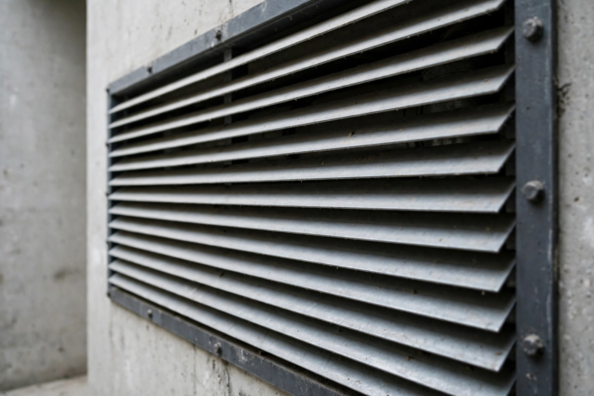
A louvre is a bank of blades. Air passes between the blades, not through the frame. The fraction that actually passes is the net free area, typically 45–60% for a weather louvre and 35–50% for an acoustic louvre, where the blades are deeper and lined with absorbent material. A 10 m² louvre bank at 50% free area passes air through 5 m². A 10 m² acoustic bank at 40% passes air through 4 m².
The conversion is simple: gross louvre area = required free area ÷ free-area fraction. For the 500 kVA set above, 4.8 m² of free area needs 9.7 m² of gross louvre at 50% free area, and 12.0 m² at 40%. The free-area fraction must come from the louvre manufacturer’s test data for the exact blade profile ordered, not from a catalogue headline. Two louvres that look identical can differ by 10 points of free area.
Screens and bird mesh cost free area as well. A standard insect screen takes 10–15% of the opening. A fine mesh fitted to keep out sand or insects in a desert or coastal site can take 25%. Measure the free area with the mesh fitted, or add the mesh loss to the gross area. A room that passed its design check on paper and then had mesh fitted over the louvre is a room that fails its first full-load test.
Face Velocity and Noise
Face velocity is the air speed through the free area: airflow divided by free area. The design figure most often used is 2.5 m/s, equivalent to about 500 feet per minute. The usual working range is 500–700 FPM (2.5–3.5 m/s). Above that range, two things go wrong. Pressure drop rises with the square of velocity, so a louvre run at 4 m/s instead of 2.5 m/s costs roughly two and a half times the pressure drop. And the louvre starts to whistle. A louvre that whistles is passing air faster than its design face velocity, and the noise is the symptom, not the fault.
Noise is the reason acoustic louvres exist, and acoustic louvres are the reason rooms get undersized. A silent generator canopy is quiet because its intake and discharge paths turn corners through baffles. A room louvre does the same job with deeper blades, and deeper blades mean less free area for the same panel. The acoustic requirement and the airflow requirement have to be solved together, on the same drawing, with the same free-area figure. Solving noise first and airflow second produces a quiet room and a derated set.
Static Pressure: The Fan’s Budget
Every restriction in the air path — louvre, duct, bend, silencer, discharge grille — costs static pressure. The radiator fan has a budget for that cost, stated on the datasheet as the maximum allowable static pressure across the radiator, typically in the range of 125–250 Pa for engine-driven fans on sets of this size. A louvre bank should hold its pressure drop under about 40 Pa at design face velocity, leaving the rest of the budget for ducts and silencers.
The check is a measurement, not a calculation. At handover, with the set at rated load, measure the static pressure across the radiator and the room temperature after 30 minutes. If the pressure is above the datasheet limit, the fan is working outside its curve and moving less air than the design assumed. If the room temperature is more than 5 K above design ambient after 30 minutes at rated load, the ventilation is not removing the heat it was sized to remove. Both readings belong in the handover record, with the load and the ambient temperature written beside them. A room that was never measured at rated load is a room whose ventilation is an opinion.
Radiant Heat: The Kilowatts the Radiator Never Sees
A diesel engine converts roughly one-third of its fuel energy into electricity. The rest becomes heat, and the heat takes three paths out of the machine. Knowing the split is what makes the room temperature predictable instead of surprising.
| Energy path | 400 kW set at full load (approx.) |
|---|---|
| Electricity delivered | ~400 kW |
| Radiator (coolant) heat | ~250–300 kW |
| Exhaust gas heat | ~150–200 kW |
| Radiant heat to the room | ~50–75 kW |
| Fuel energy in | ~950 kW |
The fuel figure is not a guess. A Cummins C500D5 at prime full load burns 93.2 litres per hour. Diesel carries about 10.25 kWh of thermal energy per litre, so the fuel energy entering the set is about 955 kW. The alternator delivers 400 kW. The remaining 550 kW leaves as heat, split between the radiator, the exhaust and the room itself.
The radiant share — 50–75 kW from the engine block, alternator, turbocharger and exhaust pipework — is the heat that stays in the room even when the radiator is ducted outside. It is also the heat that sets the room temperature during a test run at part load, when the radiator fan is moving less air. Lagging the exhaust pipework inside the room cuts the radiant figure materially; an unlagged exhaust manifold at 500°C radiates several kilowatts per square metre of surface. The lagging is cheap. The derating it prevents is not.
What does 50 kW of radiant heat do to a sealed room? Take a room of 100 m³ — about 5 m by 6 m by 3.3 m high. The air in it weighs about 120 kg. Air has a specific heat of about 1.005 kJ per kg per kelvin. 50 kW into 120 kg of air raises its temperature by roughly 0.4 K per second — about 25 K per minute — before the walls and the steel start absorbing heat. The walls do absorb heat, so the real curve bends, but the order of magnitude is the point: a sealed generator room reaches trip temperature in minutes, not hours. Ventilation is not a comfort item. It is the only thing standing between the set and its own heat.
Room temperature limits come from two places. NFPA 110 requires a Level 1 emergency power supply room to hold a minimum of 40°F (4.5°C) when the set is not running, so the engine starts and accepts load, and requires the ventilation to limit the maximum air temperature in the room to the maximum ambient the manufacturer allows — typically 40°C for a standard set, 50°C with a high-ambient radiator option. The control panel, the battery charger and the alternator windings all have their own limits, and the alternator is usually the first to complain: winding insulation ages twice as fast for every 8–10 K above its design temperature. A room that runs 10 K hot does not fail on the day. It fails the insulation two years early, and nobody connects the two events.
Layout Rules That Decide Whether the Numbers Work
A correctly sized louvre in the wrong place is still a failed room. Air follows the path of least resistance, and in a generator room the path of least resistance is usually a short circuit from the intake straight back out of the discharge, with the hot air never passing the radiator at all.
Intake Opposite Discharge
Intake and discharge belong on opposite walls, or at opposite ends of the same long wall, with the set between them. Cool air enters low at the alternator end, sweeps along the set, passes through the radiator, and leaves high at the radiator end. Hot air rises, so the discharge sits high and the intake sits low. The arrangement is not aesthetic. It is the only layout in which the air is forced to cross the machine.
The discharge area should be at least as large as the intake, and the usual design rule puts it larger: intake area not less than 1.6 times the radiator area, discharge area not less than 1.5 times the radiator area. The discharge is hotter air, and hot air occupies more volume than the same mass of cool air. A discharge smaller than the intake chokes the fan from the outlet side, which is harder to diagnose than an intake restriction because the louvre looks generous.
Ducts, Bends and Turning Vanes
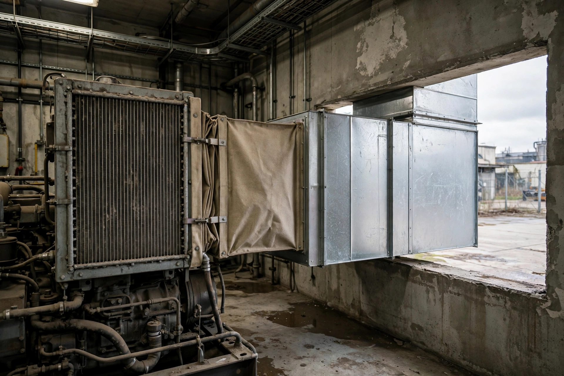
Where the radiator discharges through a duct, the duct should connect to the radiator with a flexible joint and run straight for at least one duct diameter before the first bend. Every bend adds static pressure, and a bend immediately at the radiator face adds more than the same bend further down the duct, because the air leaving the core is turbulent and uneven. Turning vanes in a bend cut the loss roughly in half. A 90-degree bend without vanes in a 12 m³/s duct can cost 30–50 Pa — a quarter of the fan’s budget — for the sake of a fitting that costs less than the fuel for one test run.
Ducts also leak. A discharge duct that leaks hot air back into the room is a short circuit the drawings never show. Seal the joints, and check the seal with the set at full load and a hand held at the joints. Hot air on the hand is a failed seal.
When the Math Does Not Close: Move the Radiator Out
Some rooms cannot be fixed with a bigger louvre. A basement room with one external wall, a room deep inside a building, a room where the only available opening faces a neighbour’s window — the ventilation arithmetic closes on paper and fails on the site. The correct answer then is not a bigger fan. It is to move the heat rejection outside.
A remote radiator puts the heat exchanger on the roof or on a ground pad outside, and coolant travels there through piping. The room still needs ventilation, but only for the 50–75 kW of radiant heat and the combustion air — roughly a tenth of the airflow a skid-mounted radiator needs. The room can shrink, the louvre can shrink, and the noise leaves with the fan. What it costs is piping, a circulating pump, a rooftop structure, and a design that gets the air out of the coolant loop. The full trade-off — when remote is right, what the piping design has to include, and what it costs — is covered in the companion article on remote radiators. The point here is narrower: if the ventilation math does not close, do not argue with physics. Move the heat rejection outside.
Three Rooms That Got It Wrong
Case 1: Hotel Basement, Lagos — One Louvre, 58°C
A hotel in Lagos installed a 500 kVA standby set in a basement plant room. The room had a single louvre, 2 m² gross, on the one external wall — about a fifth of the 9.7 m² the arithmetic in Section 2 requires. The intake and the discharge shared the same opening, separated by a sheet-metal divider that leaked.
On the first long outage the room temperature reached 58°C within 40 minutes. The set tripped on high coolant temperature at 62°C room air, restarted, and tripped again. The hotel ran on a hired portable set for the rest of the outage while the basement cooled. The fix was a second louvre cut into the opposite wall, a ducted discharge, and a divider that actually sealed. The room now holds 46°C at full load on a 38°C afternoon. The set was never the problem. The wall was.
Case 2: Data Centre, 45°C Ambient — Acoustic Louvres That Choked the Fan
A colocation data centre specified acoustic louvres for its generator rooms to meet a boundary noise limit. The louvre schedule stated the panel size, not the free area. The acoustic bank delivered 35% free area where the design had assumed 50%. At 45°C ambient the radiator fan was working against a static pressure 60 Pa above its datasheet limit, moving about 15% less air than the design figure.
The sets held load through the winter and derated on the first hot afternoon of summer, shedding load exactly when the cooling plant needed it most. The fix was a larger louvre bank — 40% more gross area — and attenuators sized on their tested free area rather than their catalogue panel size. The noise limit still holds. The difference is that the acoustic figure and the airflow figure now appear on the same line of the same schedule.
Case 3: Warehouse Retrofit, Nairobi — Intake and Discharge on the Same Wall
A warehouse in Nairobi retrofitted a 250 kVA set into a corner of the building. The only external wall was the one the set backed onto, so the intake and the discharge went into the same wall, two metres apart, at the same height. Hot discharge air curled back into the intake. Measured intake air temperature was 12 K above ambient — the set was breathing its own exhaust heat.
The effect was a silent derate. The set ran, carried load, and never tripped. But at 12 K above ambient intake temperature, the available output fell by roughly 8–10%, and the coolant temperature ran 6 K hotter than design for the life of the installation. The fix was a discharge duct run up the outside of the wall to roof level, and a turning vane at the intake. The intake temperature dropped to 2 K above ambient. Nothing about the set changed. The air path did.
Frequently Asked Questions
How much ventilation does a diesel generator room need?
A 500 kVA set needs about 12 m³/s of air at full load — 9.2 m³/s by the 48.5 CFM-per-kW rule and 12.1 m³/s by heat balance — with about 4.8 m² of louvre free area at 2.5 m/s face velocity. Smaller sets scale roughly in proportion: about 6 m³/s for 250 kVA and about 24 m³/s for 1,000 kVA. Size the room on the larger of the two methods, and add volume for altitude and hot ambient air.
How to calculate louvre size for a generator room?
Divide the design airflow in m³/s by the face velocity — usually 2.5 m/s — to get the net free area, then divide by the louvre’s free-area fraction to get the gross panel area. For a 500 kVA set: 12.1 ÷ 2.5 = 4.8 m² of free area, and 4.8 ÷ 0.50 = 9.7 m² of gross louvre at 50% free area. Use the manufacturer’s tested free-area figure for the exact blade profile, with screens and mesh fitted, and keep the louvre pressure drop under about 40 Pa.
How hot does a generator room get?
A ventilated room at full load should hold within about 5 K of design ambient after 30 minutes — typically 40–45°C on a hot day. A sealed or undersized room climbs fast: 50 kW of radiant heat raises the air in a 100 m³ room by roughly 25 K per minute before the walls absorb heat. Most sets trip on high coolant temperature when room air passes 55–60°C, and alternator insulation ages twice as fast for every 8–10 K above design temperature.
How much air does a diesel generator need for cooling?
Cooling air is about 45 CFM per kW of output, plus about 3.5 CFM per kW for combustion — roughly 48.5 CFM per kW combined, or about 0.023 m³/s per kW. A 400 kW set needs about 9.2 m³/s by this rule, and about 12.1 m³/s by heat balance at an 11°C room temperature rise. Always confirm against the engine datasheet, which states the radiator airflow and the maximum allowable static pressure for the exact set ordered.
Can a diesel generator be installed in a basement?
Yes, with conditions. A basement room needs mechanical ventilation sized on the same arithmetic — about 12 m³/s for a 500 kVA set — plus air-change rates that rise with depth: at least 3 air changes per hour for a ground-floor room, 6 for a semi-underground room and 12 for a fully underground room, with accidental ventilation at double those figures. The intake and discharge must reach outside air on opposite sides of the room, the fuel store needs its own ventilation, and if the airflow math does not close, a remote radiator is the standard answer.
Specification Checklist: Seven Numbers Before the Walls Go Up
1. Design airflow in m³/s, by both methods. Rule of thumb and heat balance, side by side, with the larger figure adopted. For a 500 kVA set, that is 12.1 m³/s. The figure belongs on the room drawing, not in a separate calculation sheet.
2. Louvre free area in m², and gross area in m². Free area at 2.5 m/s face velocity, gross area after dividing by the tested free-area fraction with screens fitted. State both figures in the louvre enquiry. A supplier who quotes panel size only has not answered the question.
3. Static pressure budget in Pa. Radiator fan limit from the datasheet, louvre drop under 40 Pa, and the balance reserved for ducts and silencers. Verify the pressure across the radiator at rated load at handover, and record it.
4. Room temperature rise in K. Acceptance figure: within 5 K of design ambient after 30 minutes at rated load. Measure it with a load bank testing run at full load, not at no load. A room that passes at no load has proved nothing.
5. Intake and discharge positions. Opposite walls, intake low at the alternator end, discharge high at the radiator end. Discharge area at least equal to intake area. No shared opening, no discharge beside the intake.
6. Minimum room temperature and fire rating. NFPA 110 Level 1 requires 4.5°C minimum in the room and a 2-hour fire-rated enclosure for an indoor emergency power supply, with 36 inches of working clearance around the set for inspection and repair. A cold room that will not start is as much a failure as a hot room that trips.
7. The fuel store and the day tank. Fuel tank sizing for the required autonomy — 72 hours is the usual figure for a site that cannot guarantee delivery — with the tank’s own ventilation and spill containment. A day tank inside the room adds heat and a fire load; its ventilation is part of the room calculation, not an afterthought.
A generator room is the cheapest part of a generator installation and the most common reason the installation fails. The steel, the concrete and the louvre together cost less than the fuel for a year of testing. The arithmetic that sizes them takes an afternoon. Do it before the walls go up, because a louvre that is too small is a structural defect, and structural defects are the ones that get lived with until the first long outage exposes them.
For a room layout or a set sized to a specific site — altitude, maximum ambient temperature, duty and the largest single motor — contact PAVO with the room dimensions and the load list, and the ventilation figures will come back with the quotation, not after it.