

What Size Generator Does a Battery Gigafactory Need? | PAVO
A gigafactory is not a factory with a bigger generator. It is a 200-megawatt chemical process that happens to have walls, and the generator is there to protect the parts that cannot stop — not to carry the plant.
What size generator does a battery gigafactory need? A 10 GWh plant needs 4,000–8,000 kVA of prime-rated backup for its critical loads — dry rooms, formation hold, gas detection and fire systems — while a 40 GWh plant needs 15,000–30,000 kVA. No diesel set carries the whole plant: a 40 GWh site draws 200–400 MW.
This article works through the load list of a real gigafactory, the critical slice a diesel set can actually protect, the sizing table by plant capacity, the dry-room dew-point clock, the formation load that never sleeps, and three outages that show what a short gap costs when the product is a lithium-ion cell. It covers LFP and NMC chemistries, cylindrical, prismatic and pouch formats, and the fire and gas systems that make backup power a safety question before it is a production question.
Contents
- The Honest Limit: What a Generator Can and Cannot Do in a Gigafactory
- The Loads That Must Not Stop
- Sizing the Critical Slice
- The Dry Room Cannot Breathe Wet Air
- Formation: The Load That Never Sleeps
- Three Gigafactories, Three Outages
- Frequently Asked Questions
- Specification Checklist
The Honest Limit: What a Generator Can and Cannot Do in a Gigafactory
A battery gigafactory is defined, in the power-systems literature, as a lithium-ion cell plant with more than 1 GWh of annual capacity. The plants being built now are far larger. A typical 40 GWh facility draws 200–400 MW — the electrical load of a small city — and global lithium-ion production is projected to reach about 2,200 GWh by 2030. Construction capital runs $1–5 billion, the build takes 24–36 months, and ramping to nameplate capacity adds another 18–24 months.
Those numbers set the first rule of gigafactory backup power: the generator does not back up the factory. It backs up a slice of it. PAVO’s largest standard sets reach 3,750 kVA. Eight of them in parallel deliver roughly 24 MW — about 6–12% of a 40 GWh plant’s draw. Even a row of containerised sets the length of a football pitch cannot carry electrode coating, drying ovens, dry rooms and formation at the same time. Any quotation that promises whole-plant backup for a gigafactory is either quoting a power station or misunderstanding the load.
Backup power in a gigafactory therefore means something narrower and more precise than it means in a hotel or a warehouse. It means three things, in this order. First, keep people safe: fire detection and suppression, gas detection and extraction, emergency lighting and egress. Second, keep the product safe: hold the dry rooms at dew point, hold formation racks in a known state, keep electrolyte handling contained. Third, keep the restart possible: protect the control systems, the process data and the utilities so the plant can come back in hours instead of days.
The distinction matters because the cost of failure is measured in product, not in downtime alone. Manufacturing a single 24 kWh battery pack consumes 16.31 MWh of energy. A dry room full of exposed electrodes, a formation hall full of half-charged cells, a coating line full of wet slurry — each of these is work in progress that a power failure can turn into scrap in minutes. The generator’s job is to buy time for the loads that decide whether that work survives.
The second rule follows from the first: the backup system is designed around the critical load study, not around a kVA figure picked from a brochure. The study lists every load in the plant, classifies it by what happens if it stops, and sizes the generator for the loads that cannot stop. Everything else is shed. A gigafactory that tries to back up everything ends up backing up nothing, because the generator trips on overload during the first transfer and the loads that mattered lose power with the rest.
The third rule is about time. A gigafactory outage is not a single event. It is a sequence: the grid fails, the automatic transfer switch transfers in seconds, the generator starts and accepts load in steps, the critical loads come back in priority order, and the plant either holds its state or starts losing product. The 10-second gap between grid failure and generator power is the same gap every standby site faces, but in a gigafactory the gap is measured against a dry room that is already drifting and a formation hall that is already counting down. The transfer time, the step-loading sequence and the load-shedding logic are part of the sizing exercise, not an afterthought.
The Loads That Must Not Stop
A gigafactory load list runs to hundreds of items, from a 5 kW airlock fan to a 2 MW formation rectifier. The only useful way to size backup power is to sort them into tiers by consequence, and to be honest about what each tier costs to protect.
| Tier | Loads | Allowed interruption | Typical critical load |
|---|---|---|---|
| Tier 1 — life safety | Fire detection and suppression, gas detection, extraction fans, emergency lighting, egress, alarms | Zero — UPS bridge, then generator | 200–600 kW |
| Tier 2 — process protection | Dry-room dehumidification, formation hold, electrolyte handling, coating-line safe stop, cleanroom pressurisation | Seconds — ATS transfer only | 2–15 MW |
| Tier 3 — restart and utilities | Compressed air, process water, chilled water, IT/OT and MES, control rooms, lighting | Minutes — sequenced restart | 1–5 MW |
Tier 1 is non-negotiable and it is small. Fire detection, gas detection, extraction fans, emergency lighting and the alarm system together draw a few hundred kilowatts on a large plant, and they sit behind a UPS that bridges the transfer gap. The UPS is not there to run the plant. It is there to hold the safety systems alive for the 10 seconds the generator needs to start, and to keep the control systems coherent while the transfer happens. A Tier 1 load that drops for even a second is a safety failure, and in a plant handling flammable electrolyte and hydrogen fluoride risk, a safety failure is the one outcome no production target justifies.
Tier 1 — life safety, fire systems and gas detection
The electrolyte in a lithium-ion cell is a flammable organic solvent, and the gas it gives off under abuse includes hydrogen fluoride. A gigafactory therefore runs gas detection and extraction as a continuous safety system, not as a process utility. Detectors sit over the electrolyte filling lines, the formation wings and the electrolyte storage areas. Extraction fans hold those zones at negative pressure so that a leak goes up the stack instead of across the hall. If the fans stop, the gas has nowhere to go.
Fire protection follows the same logic. Formation and ageing carry the highest concentrated fire risk in modern manufacturing, and the standard that governs them is NFPA 855, the standard for the installation of stationary energy storage systems. Clean-agent suppression does not stop thermal runaway in a lithium-ion cell; the standard calls for water-based suppression, isolated formation wings and reinforced firewalls. The pumps, the detection loops and the valve controls for that suppression system are Tier 1 loads. They draw little power and they must never lose it.
Tier 2 — process protection: dry rooms, formation hold, electrolyte handling
Tier 2 is where the money sits. The dry room is the largest single protected load: a gigafactory dry room runs 100 or more dehumidification units, each moving up to 50,000 m³/h of air, holding a hall of 10,000–48,000 m² at a dew point of −40 to −60 °C. The formation hall is the second: thousands of cells on charge at once, each rack drawing steady current for 20 hours at a time. Electrolyte handling — filling lines, storage, dosing — is the third: a line that stops mid-fill leaves open cells exposed to air and a dosing system that has to be purged and re-qualified before it can run again.
Tier 2 loads tolerate the ATS transfer gap but nothing longer. A dry room that loses its dehumidification for 15 minutes is a dry room that has to be re-dried and re-qualified. A formation hall that loses power mid-cycle is a hall full of cells whose first charge was interrupted. The generator for Tier 2 is sized for the full Tier 2 load plus the starting surge of the largest motors, and it is stepped on in priority order: gas extraction and fire systems first, then dry-room dehumidification, then formation hold, then the rest.
Tier 3 — restart and utilities: compressed air, water, IT and controls
Tier 3 is everything the plant needs to restart cleanly. Compressed air for the pneumatic actuators and the airlocks. Process water and chilled water for the coating lines and the cooling circuits. The IT and OT systems — the manufacturing execution system, the process historians, the quality database — that hold the record of every cell. Control rooms and lighting for the crews who will run the restart.
Tier 3 loads can wait minutes, and they are the loads that get shed first when the generator is undersized for the moment. But they cannot wait hours. A plant that restarts without its MES has no record of which cells were in formation when the power failed, and a plant that restarts without compressed air cannot run its airlocks. The sizing exercise has to include Tier 3, even if Tier 3 is the last load stepped on, because a restart without it is a second outage.
Sizing the Critical Slice
The sizing table below is built from the one hard number in the public literature — a 40 GWh plant draws 200–400 MW — and scaled down by capacity. The critical slice is the Tier 1 plus Tier 2 load, and it runs at roughly 5–8% of the plant’s full draw. That is the load the generator must carry. Everything else is shed on transfer.
| Plant capacity (GWh/year) | Full plant load (MW) | Critical load (MW) | Generator provision |
|---|---|---|---|
| 5 GWh | 25–50 | 2–4 | 2 × 1,250 kVA prime, N+1 |
| 10 GWh | 50–100 | 4–8 | 3 × 2,500 kVA prime, N+1 |
| 20 GWh | 100–200 | 8–15 | 4 × 2,500 kVA prime, 11 kV |
| 40 GWh | 200–400 | 15–30 | 6–8 × 3,125 kVA prime, 11 kV paralleled |
The table is a planning starting point, not a quotation. Two plants with the same GWh figure can differ by a third once the chemistry and format are known. An NMC plant with a −60 °C dry room and a large formation hall carries a heavier critical load than an LFP plant of the same capacity with a −40 °C dry room. A cylindrical-cell plant with high-speed winding lines carries a different load profile from a pouch-cell plant with stacking lines. The sizing exercise has to start from the actual load list of the plant being built, not from the GWh headline.
The worked example: a 10 GWh plant
Take a 10 GWh LFP plant. The load study puts Tier 1 at 400 kW and Tier 2 at 5,200 kW: dry-room dehumidification 2,800 kW, formation hold 1,600 kW, electrolyte handling and cleanroom pressurisation 800 kW. Tier 3 adds 1,400 kW of compressed air, water and IT that must come back within minutes. The generator must carry 5,600 kW immediately and 7,000 kW once Tier 3 is stepped on.
Convert to kVA at 0.8 power factor: 7,000 kW is 8,750 kVA. Add a 10% margin for load growth and instrument error, and the prime requirement is 9,600 kVA. The practical choice is four 2,500 kVA prime sets in parallel, one of them as N+1 reserve, so that the loss of any one set still leaves 7,500 kVA — enough for Tier 1 and Tier 2 with Tier 3 shed. The full method — running load, starting surge, diversity and growth margin — is set out in the generator sizing guide.
The rating matters as much as the figure. A gigafactory outage is not a 200-hour-a-year standby event. A plant in a region with an unreliable grid, or a plant running a long commissioning programme, can put 1,000–2,000 hours a year on its backup sets. That is prime power duty, and the difference between standby and prime ratings is the first thing to settle in any quotation. A standby-rated set run as a prime set voids the warranty and shortens its life by years, and a gigafactory that discovers that in year three has a backup system it cannot trust.
Starting surge: the dehumidification fans and the chillers
The critical load is a running figure. The starting figure is larger, and it is the figure that trips generators. A dry-room dehumidification unit is a fan and a desiccant wheel: the fan motor draws four to seven times its rated current at start, and a hall with a hundred units cannot start them all at once. The same applies to the chillers, the compressors and the cleanroom air-handling fans. The rule for motor starting on a gigafactory is the same as on any industrial site — the largest motor starts first, against the lightest load — but the scale is larger and the sequence is longer.
The practical answer is a step-loading sequence written into the generator controller and tested at commissioning. Tier 1 loads come on first, on the UPS bridge. Then the dry-room dehumidification fans, started in groups of ten with 30-second gaps. Then the formation rectifiers, ramped up rather than switched on. Then Tier 3, one utility at a time. A sequence that takes 8–12 minutes to complete is normal for a plant of this size, and it is the reason the transfer switch and the load-shedding logic are specified together with the generator, not bought separately.
Variable-frequency drives change the arithmetic but do not remove it. A VFD-fed fan starts softly, drawing little more than running current, and most new gigafactories specify VFDs on the large air-handling motors for exactly that reason. But a VFD is itself a non-linear load, and a hall full of VFDs and formation rectifiers puts harmonics onto the generator bus. The alternator has to be sized for the harmonic content, not just the kW figure, and the subtransient reactance of the alternator decides how far the voltage dips when the largest remaining direct-on-line motor starts. The harmonic study belongs in the sizing exercise, before the alternator is ordered.
Fuel autonomy: the 72-hour question
A generator that runs out of fuel is a generator that never existed. The fuel calculation for a gigafactory is straightforward and unforgiving. A 2,500 kVA prime set at 75% load draws about 2,000 kW, and at a typical 0.21 litres per kWh that is roughly 420 litres per hour. Four sets at 75% load burn about 1,680 litres per hour, or 40,000 litres a day. A 72-hour autonomy target — the figure most gigafactory operators specify, because a grid failure that lasts three days is the failure worth planning for — needs roughly 120,000 litres of usable fuel on site, plus a contracted delivery plan that can top the tanks up while the outage is still running.
The reference point is a smaller, published datasheet. The Cummins C500D5 — 500 kVA standby / 455 kVA prime — burns 93.2 litres per hour at full prime load. Scale that figure and the arithmetic holds: a gigafactory backup system is a fuel-logistics operation as much as an electrical one. The bulk tank, the transfer pumps, the fuel polishing and the delivery contract are part of the specification, and diesel fuel ageing in a tank that sits for months between outages is a maintenance item, not a detail. A tank of stale fuel is the most common reason a well-sized generator fails on the night it is needed.
Why 11 kV for the large plants
Above about 8,000 kVA of prime provision, the generator bus moves to medium voltage. Four 2,500 kVA sets at 400 V would need busbars and switchgear carrying 14,000 A — a physical and cost problem. At 11 kV the same power is 525 A. The large gigafactory backup systems are therefore 11 kV systems: the sets generate at 11 kV, the step-down transformers feed the 400 V critical distribution, and the paralleling switchgear is medium-voltage equipment with the protection and synchronisation that goes with it. The generator supplier and the switchgear supplier have to be in the same room during design, because the protection settings on one side decide the fault behaviour on the other.
The Dry Room Cannot Breathe Wet Air
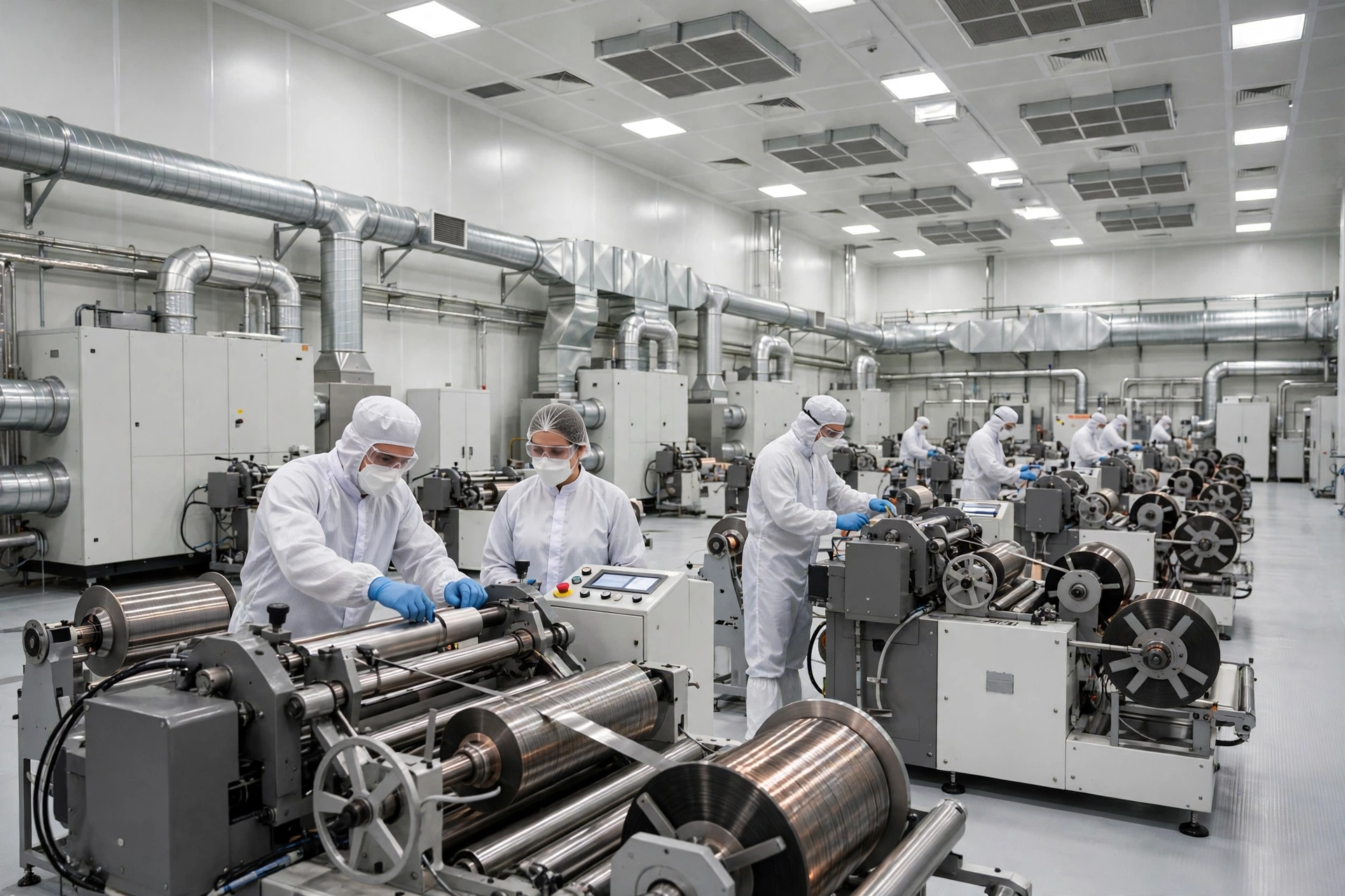
The dry room is the signature engineering challenge of every gigafactory, and it is the load that punishes a power failure fastest. Cell assembly — winding or stacking the electrodes, welding the tabs, injecting the electrolyte, sealing the cell — happens in air held at a dew point of −40 to −60 °C, drier than the driest desert on Earth. For nickel-rich NMC cathodes and solid-state chemistries the requirement tightens to −70 or −80 °C. A single gigafactory dry room covers 10,000–48,000 m² and runs 100 or more dehumidification units, each moving up to 50,000 m³/h of air through desiccant wheels and vapour barriers, behind airlocks that keep the outside world out.
The dry room is also the load that decides whether a 10-minute outage becomes a lost shift. The discipline is the same as in semiconductor fab backup power: a controlled environment that loses its envelope has to be re-qualified before production restarts. The dehumidification units stop, the airlocks keep working on UPS for a while, and the dew point starts to rise. The room is a sealed envelope, so the rise is slow at first — infiltration through the airlocks and the fabric of the building, moisture from the people and the materials inside. Operators plan on a 15–30 minute window before the dew point crosses the −40 °C limit in a large hall, and a shorter window in a small one. After that, the room is out of specification, and everything inside it is suspect.
What moisture does in minutes
Moisture is not a comfort problem in a dry room. It is a yield problem, and a safety problem. Water in the air reacts with the lithium-containing electrode materials and with the electrolyte salt, lithium hexafluorophosphate. The reaction produces hydrogen fluoride, which attacks the electrodes and the current collectors, and it produces capacity loss that no amount of formation cycling recovers. A cell assembled in air above the dew-point limit does not fail on the test bench. It fails in the customer’s product, months later, as a cell with lower capacity and higher internal resistance than its batch mates.
The damage is invisible at the time and irreversible afterwards. That is why the dry-room specification is written as a dew point, not as a humidity percentage, and why the monitoring is continuous. A dry room that has been out of specification for 20 minutes does not get a second chance: the exposed electrodes and the open cells are scrapped, the room is re-dried, and the quality team re-qualifies the hall before production restarts. The scrap cost of a single excursion in a large dry room runs to tens of thousands of dollars in materials alone. The re-qualification cost — lost production, re-testing, documentation — is larger.
The generator’s job in the dry room is therefore not to keep the room comfortable. It is to keep the dehumidification units running through the transfer gap and to keep them running for as long as the outage lasts. The units restart in sequence, the largest fans first, and the room is held at dew point while the rest of the plant waits. A dry room that never leaves specification is a dry room that never has to be re-qualified, and that single fact is worth more than any other line in the backup specification.
The restart sequence after a dew-point excursion
When the dew point has crossed the limit, the restart is a procedure, not a switch. First the dehumidification units come back to full output and the room is pulled back to −40 °C or below, a process that takes 1–3 hours depending on the size of the hall and the moisture load. Then the air is sampled and the dew point is verified at multiple points, not just at the sensor by the door. Then the exposed work in progress is dispositioned: electrodes and open cells are scrapped, sealed cells are held for additional testing, and the batch record is annotated.
Only then does production restart, and it restarts slowly. The first cells off the line after an excursion go through extended testing — capacity, internal resistance, self-discharge — before they are released. A plant that restarts in a hurry after a dew-point excursion ships cells it cannot stand behind, and a gigafactory that ships cells it cannot stand behind does not stay in business for long. The generator, the UPS and the transfer sequence exist so that this procedure is never needed.
Formation: The Load That Never Sleeps
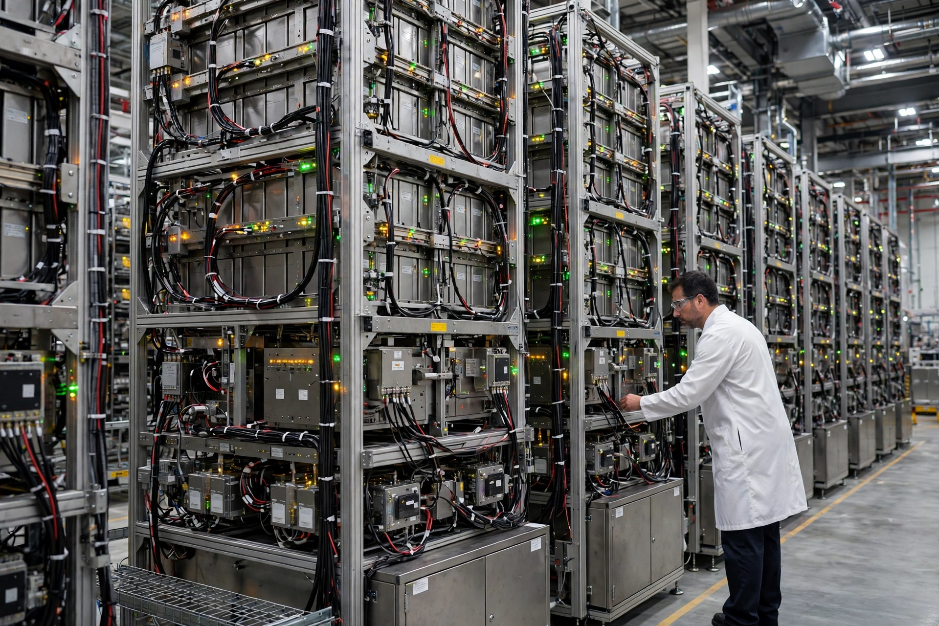
Formation is the first charge of a new cell, and it is the most energy-hungry step in the whole factory. A cell is charged and discharged for the first time to form the solid electrolyte interphase — the SEI layer — on the anode, and then it is aged for days while its voltage is monitored for self-discharge. Formation consumes about 26% of the energy per cell produced, alongside coating and drying and the dry rooms, and it accounts for 20–30% of the total cost of the battery. A formation cycle at 0.1C takes up to 20 hours, and a gigafactory has tens of thousands of cells in formation at any moment.
The load is large, steady and intolerant of interruption. A formation hall does not have peaks and troughs. It has thousands of racks drawing current around the clock, and the current and voltage on each channel are controlled to better than ±0.02%. That precision is the reason formation is a power-quality problem as well as a power problem: a voltage dip or a harmonic distortion that a motor would ignore can push a formation channel out of tolerance and invalidate the data for a whole batch.
Why formation cannot pause
A formation cycle interrupted mid-charge does not resume where it stopped. The SEI layer forms in the first hours of the first charge, and its quality decides the cell’s life: a well-formed SEI gives a cell that holds capacity for thousands of cycles, and a poorly formed SEI gives a cell that fades early and runs hot. Interrupting the cycle part-way through leaves a partially formed SEI, and the cell has to be dispositioned — reworked through a new cycle if the process allows it, or scrapped if it does not.
The cost is not one cell. It is a hall full of them. A formation wing holds 20,000–50,000 cells at a time on a large plant, and a 10-minute outage that drops the hall puts every one of those cells into question. The quality team has to decide, channel by channel, which cells can be re-run and which are scrap, and the formation data for the affected batches is annotated for the customer. A gigafactory that sells cells into electric vehicles or grid storage does not get to guess at this. The formation record is part of the product.
The generator’s job in the formation hall is to hold the racks in a known state. The rectifiers are ramped down in a controlled sequence on transfer, the UPS holds the control and data systems, and the generator picks the hall up in stages. A formation hall that never loses its control power is a hall whose cells can be dispositioned from data instead of from guesswork, and that distinction is worth more than the fuel the generator burns.
Regenerative discharge and power quality
Modern formation equipment is regenerative: the energy discharged from a cell during the discharge half of the cycle is returned to the DC bus instead of being burned off as heat. A well-designed regenerative system returns a large share of the discharge energy, which is why formation halls are specified with DC distribution alongside the AC supply. The generator and the formation rectifiers therefore share a bus that carries power in both directions, and the harmonic content of that bus is a design input, not a surprise.
The rectifiers are non-linear loads, and a hall full of them puts harmonics onto the generator bus in the same way a hall full of VFDs does. The alternator has to be sized for the harmonic heating, the neutral has to be sized for the triplen harmonics, and the voltage waveform has to stay clean enough for the ±0.02% formation accuracy. The harmonic study for a formation hall is a specialist exercise, and it is done before the alternator is ordered, because an alternator that is too small for the harmonic load runs hot, distorts the waveform and shortens its own life. The practical rule is the one set out in the site’s harmonics guide: size the alternator for the distorted load, not for the kW figure on the nameplate.
The formation-wing fire risk
Formation and ageing carry the highest concentrated fire risk in modern manufacturing, and the fire protection for a formation wing is designed around that fact. A cell in thermal runaway cannot be stopped by a clean agent: the reaction generates its own oxygen and its own heat, and the agent suppresses the flame without stopping the cell. The standard — NFPA 855 — calls for water-based suppression, isolated wings and reinforced firewalls, so that a runaway in one wing stays in that wing.
The backup system has to serve that design. The fire pumps, the detection loops, the valve controls and the extraction fans are Tier 1 loads, and they are specified to run on generator power for the full duration of an incident, not for a 10-minute bridge. A formation wing that loses its suppression water pressure during a thermal event is a wing that burns, and a wing that burns is a plant that stops for months. The fire system is the smallest load on the generator and the most important one.
Three Gigafactories, Three Outages
Case 1: a 20 GWh LFP plant in Nevada — 12 minutes that cost a dry room
A 20 GWh LFP plant in Nevada, built on a greenfield site outside Sparks, runs two dry rooms of 18,000 m² each and a formation hall of 30,000 cells. The plant’s grid supply is a dedicated 138 kV feed, and the backup system is four 2,500 kVA prime sets behind a closed-transition transfer switch, sized for the 9 MW critical load.
A summer thunderstorm dropped the 138 kV feed at 14:20 on a Tuesday. The transfer switch moved in 9 seconds and the sets picked up Tier 1 and the dry-room dehumidification in sequence. The fault was not in the transfer. It was in the sequence: the dehumidification fans in the second dry room were stepped on in the third group, 11 minutes after the transfer, because the formation rectifiers had been given priority in the step-loading order. In those 11 minutes the dew point in the second hall rose from −52 °C to −38 °C, crossing the plant’s −40 °C limit.
The consequence was a full re-qualification of the hall. 4,200 electrode stacks were scrapped, the room was re-dried over 3 hours, and the first cells off the line went through extended testing before release. The direct cost was about $180,000 in materials and lost production. The fix was a reordering of the step sequence: dry-room dehumidification now steps on in the first group, ahead of formation, because a dry room that drifts costs more than a formation hall that waits. The plant’s backup sets were never the problem. The order in which they were loaded was.
Case 2: a 15 GWh NMC plant in northern Sweden — a winter storm and a formation hold
A 15 GWh NMC plant in northern Sweden, built to supply European car makers, runs a −60 °C dry room and a formation hall sized for 40,000 cells. The site’s winter design temperature is −30 °C, and the plant’s backup system is three 2,500 kVA prime sets with a 72-hour fuel autonomy target, because a winter grid failure in the far north is measured in days, not hours.
A January storm took down the regional grid for 31 hours. The sets started on the first crank — the block heaters and the battery chargers had been maintained through the autumn, and the fuel was winter-grade diesel with the cloud point specified for −30 °C. The critical load held at 6,800 kW for the whole outage: dry rooms at −60 °C, formation hold on the racks that could not be paused, gas detection and extraction throughout.
The plant lost no cells. It lost two days of production on the lines that were shed — coating and drying, which were stopped deliberately and restarted in sequence — and it spent $42,000 on fuel. The lesson the plant took from the outage was about the fuel, not the generators: the 72-hour autonomy target had been calculated at 75% load, and the actual load ran at 82% because the formation hold drew more than the study had allowed. The tanks reached 28% with 12 hours of outage still to run, and the contracted fuel delivery arrived with four hours to spare. The plant now sizes its fuel for the measured load, not the studied load, and keeps a 96-hour target in winter.
Case 3: a 30 GWh plant in Jiangsu — a summer peak and a staged shed
A 30 GWh plant in Jiangsu, China, runs three shifts through the summer, when the regional grid is at its tightest and the plant’s own cooling load is at its highest. The backup system is six 3,125 kVA prime sets at 11 kV, sized for a 16 MW critical load, with a load-shedding scheme that drops the coating lines first and the dry rooms last.
A grid fault during a July heatwave dropped the plant at 35 °C ambient. The sets started and the shedding scheme worked as designed: coating and drying stopped, the dry rooms held at −45 °C, and formation held on the racks. The fault was in the restart. The plant’s cooling towers had been shed with Tier 3, and when the grid returned 6 hours later the towers needed 40 minutes to bring the chilled-water loop back to temperature. The coating lines could not restart until the loop was cold, and the plant lost another 90 minutes of production after the power was back.
The plant’s fix was to move the chilled-water pumps into Tier 2, so that the cooling loop is held through an outage instead of being restarted after it. The additional load was 900 kW, and the generator provision absorbed it inside the existing N+1 margin. The lesson is a general one: the restart is part of the outage, and a load that decides how fast the plant comes back belongs in the protected set even if it is not a load that decides whether the product survives.
Frequently Asked Questions
What size generator does a battery gigafactory need?
A 10 GWh plant needs 4,000–8,000 kVA of prime-rated backup for its critical loads, and a 40 GWh plant needs 15,000–30,000 kVA. The figure depends on the chemistry, the dry-room dew point and the size of the formation hall, so it comes from a critical-load study rather than from the plant’s GWh headline.
Do battery gigafactories need a backup generator?
Yes. A gigafactory needs backup power for life safety, for the dry rooms and formation halls that hold work in progress, and for the systems that make a restart possible. The generator does not carry the whole plant — a 40 GWh site draws 200–400 MW — but it protects the slice whose failure turns an outage into scrap, a fire risk or a week-long restart.
How long can a gigafactory run on a generator?
A gigafactory can run its critical loads on generator power for as long as its fuel lasts, and most operators specify 72 hours of on-site fuel autonomy. The full plant cannot run on generators at all: the critical slice is 5–8% of the plant’s draw, and the rest is shed on transfer until the grid returns.
What happens to a battery factory during a power outage?
The dry rooms start to drift above their dew-point limit within 15–30 minutes, formation cycles are interrupted and the affected cells have to be dispositioned, and the coating lines stop with wet slurry in the system. The safety systems — fire suppression, gas detection and extraction — must keep running, which is why they sit behind a UPS and a generator rather than behind the grid alone.
Can a diesel generator power a battery gigafactory?
A diesel generator can power the critical loads of a battery gigafactory — dry rooms, formation hold, gas detection, fire systems and restart utilities — but it cannot power the whole plant. A 40 GWh plant draws 200–400 MW, so the backup system is sized for the 15–30 MW critical slice, in prime-rated sets paralleled at 11 kV.
Specification Checklist
| Item | Specification | Notes |
|---|---|---|
| Critical-load study | Tier 1 / 2 / 3 classification of every load | Done before the kVA figure, not after it |
| Generator rating | Prime (PRP), not standby | 1,000–2,000 hours a year is prime duty |
| Configuration | N+1 paralleled sets | Loss of one set must leave Tier 1 + Tier 2 covered |
| Voltage | 11 kV above ~8,000 kVA | 400 V busbars become impractical at gigafactory scale |
| Transfer | Closed-transition ATS, 10-second transfer | UPS bridges the gap for Tier 1 |
| Step-loading sequence | Dry-room dehumidification first, formation second | Written into the controller and tested at commissioning |
| Fuel autonomy | 72 hours at measured load, 96 hours in winter | Sized on measured load, with a contracted delivery plan |
| Fuel quality | Winter-grade diesel, polished and tested | Diesel fuel ageing kills more backup systems than engine faults |
| Harmonic study | Alternator sized for VFD and rectifier load | Formation rectifiers are non-linear loads |
| Fire protection | NFPA 855, water-based suppression, isolated wings | Fire pumps and detection on Tier 1 |
| Maintenance | Monthly load test, quarterly full-load test | Set out in the generator maintenance schedule |
| Acceptance | Witnessed factory test and site acceptance test | Formation accuracy and step sequence verified under load |
A gigafactory backup system is not a purchase. It is a design exercise that starts with the load study and ends with a tested sequence, and the generator is only one part of it. The plants that survive an outage are the ones that decided, before the outage, which loads matter and in what order they come back. The plants that lose a shift are the ones that bought kVA and hoped for the best.
To size a generator for a gigafactory — or to review the critical-load study for a plant already in design — contact PAVO. The engineering team works from the plant’s actual load list, not from a brochure figure, and sizes the sets, the switchgear and the fuel system as one installation.