

What Size Generator Does a Foundry Need? Guide | PAVO
A foundry does not stop politely when the grid fails. It stops with tonnes of molten metal at 1,450°C, a furnace lining that starts cooling the moment the power dies, and a crucible that will not wait for the utility to come back.
What size generator does a foundry need? A small jobbing foundry with a 1–2 tonne induction furnace typically needs a 200–250 kVA set for its essential board, a medium induction foundry melting 3–5 tonnes needs 400–600 kVA, and a large integrated foundry needs 800–1,250 kVA for cooling, cranes and utilities. The melt itself is never on the generator.
Contents
- The Honest Limit: What a Diesel Generator Can and Cannot Do in a Foundry
- The Foundry Load Tiers: What Must Stay On and What Can Stop
- What Size Generator Does a Foundry Need?
- What Happens in the First Hour After the Power Fails
- Three Foundries, Three Outages
- Induction Furnaces, Harmonics and the Cooling-Water Rule
- Frequently Asked Questions
- Specification Checklist: Eight Lines Before the Deposit
The Honest Limit: What a Diesel Generator Can and Cannot Do in a Foundry
Every other industrial buyer sizes a generator from the running load. A foundry cannot. The load that defines the plant — the melt — is the one load a diesel set cannot carry, and any quotation that pretends otherwise is either dishonest or wrong. The first decision in a foundry generator project is therefore a subtraction: take the plant’s connected load, remove the melting load entirely, and size the set from what remains. Most foundry owners who have lived through an outage already know this. The ones who learn it from a quotation usually learn it expensively.
Why the Melt Load Is Out of Reach
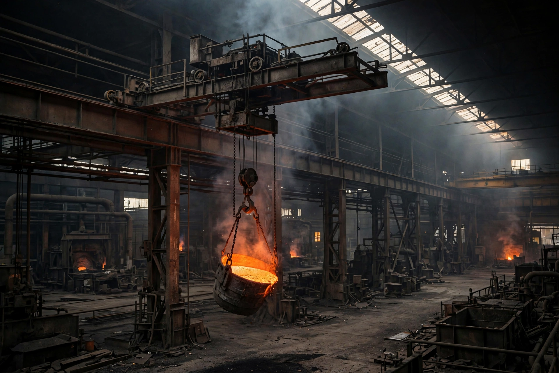
A medium-frequency coreless induction furnace of a few tonnes draws one to several megawatts through its converter. A 5-tonne furnace typically pulls 2,500–3,500 kW while melting. An electric arc furnace draws tens of megawatts. No standby diesel set in the PAVO range — and no practical number of them — covers that load, and paralleling ten 1,250 kVA sets to keep one furnace melting would cost more than the furnace, the building and a year of lost production combined. The melt stops when the grid fails. That is not a design failure. It is the physics of the process, and the generator specification has to start from it.
The same arithmetic applies to the rest of the heavy melting plant. A cupola’s coke charge keeps burning without electricity, but its blast air comes from a blower that draws 75–200 kW and its charging and tapping equipment is electrically driven. A rotary furnace, a reverberatory furnace and a holding furnace all sit in the same position: the heat source is not the problem, the electrically driven auxiliaries around it are. The generator’s job begins where the melt’s own power ends.
What the Generator Actually Protects
What the set protects is the equipment that keeps people and plant safe while the heat is still there. The list is short, specific and non-negotiable: furnace coil and converter cooling-water pumps, tilt hydraulics that let a furnace pour out or hold at a safe angle, ladle and charging cranes, fume extraction and baghouse fans, moulding-line lubrication and control power, compressed air for instruments, and the PLCs and furnace instrumentation that run the safe-state sequence. A plant that sizes for this subset typically needs 200–1,250 kVA, depending on furnace size — a fraction of the plant’s connected load, and a figure that a single set can actually deliver.
The distinction matters because it changes the entire project. A 2,000 kVA foundry may need 2,000 kVA of generation for full production continuity, 600 kVA for selected-load continuity and 250 kVA for safe shutdown and restart. Those are three different generator projects with three different prices, and the foundry’s production manager — not the electrical contractor — should decide which one applies. Most foundries choose the middle scope: cooling, cranes, extraction and controls on the essential board, production lines stopped, restart sequenced when the grid returns.
The Foundry Load Tiers: What Must Stay On and What Can Stop
A foundry’s loads fall into three tiers, and the tier decides the set size more than any nameplate total. The tiers are drawn from what happens to each load when the power fails, not from how much power it draws when running.
| Tier | Loads | Tolerable gap | On the generator? |
|---|---|---|---|
| 1 — Safety and asset protection | Induction coil and converter cooling pumps, tilt hydraulics, furnace instrumentation and PLCs, emergency lighting | Seconds | Yes, first load step |
| 2 — Restart and recovery | Ladle and charging cranes, fume extraction and baghouse fans, moulding-line controls, compressed air, water treatment | Minutes | Yes, staged after cooling |
| 3 — Production continuity | Melting furnaces, moulding machines, sand plant, shot blasting, heat treatment, fettling | Cannot be carried | No — stopped until the grid returns |
Tier 1: Safety and Asset Protection
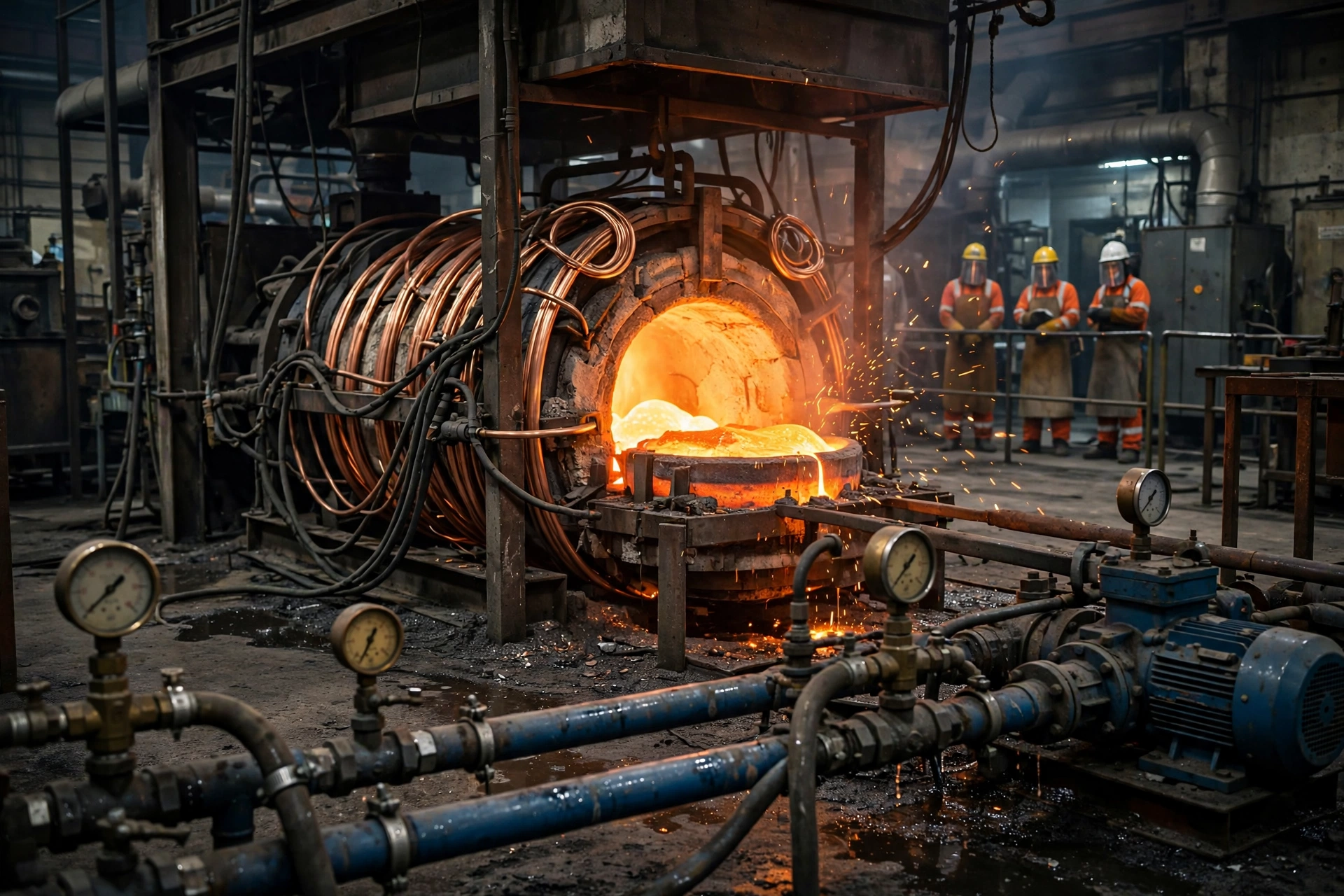
Tier 1 is the reason the generator exists. Induction furnace coils, converter cabinets and capacitor banks are water cooled, and the manufacturers specify how long cooling may be interrupted. That interval is short — measured in minutes, not hours — and a well-designed melt shop does not rely on the diesel generator alone to meet it. The usual arrangement is an elevated emergency header tank that gravity-feeds the coil for the generator start interval, or a diesel engine-driven pump that starts independently, with the electric pumps returning on the generator. The generator then carries those pumps as its first load step.
The cost of getting Tier 1 wrong is the cost of a furnace. A coil that loses cooling with a full crucible of molten iron can be damaged beyond repair within minutes, and a furnace that freezes full — metal solidifying inside the crucible — needs a new lining at $15,000–$40,000 for a 5-tonne furnace, plus 7–10 days of lost melting while the lining is stripped, relined and cured. A large furnace that freezes can cost $100,000 or more to rebuild. The generator that prevents it costs a fraction of that, once.
Tier 2: Restart and Recovery
Tier 2 loads are the ones that decide how fast the foundry restarts, and how much of the shift is lost. A ladle crane that cannot move leaves a ladle of cooling metal hanging over the melt shop floor. Fume extraction that stops while the metal is still hot leaves the shop filling with smoke and silica dust. Moulding-line controls that lose power leave moulds half-made and sand in the conveyors. None of these loads is a matter of life and death in the first minute, but all of them are on the generator’s second and third load steps, staged a few seconds apart so the set never sees them as a single block.
Tier 3: Production Continuity
Tier 3 is everything that stops. Melting furnaces, automatic moulding machines, the sand plant, shot-blast machines, heat-treatment furnaces and fettling bays all come off the essential board. The decision is usually made once, written into the automatic transfer switch logic, and then never revisited on the night of an outage. A foundry that tries to keep Tier 3 loads on a standby set ends up with a set that trips on the first motor start and protects nothing — the worst possible outcome, because the Tier 1 loads go down with it.
What Size Generator Does a Foundry Need?
The sizing method is the same one used for every industrial plant, applied to the Tier 1 and Tier 2 loads only. List the loads that must run at the same time, total their running kW, divide by the power factor, then add the starting kVA of the largest motor that will start while the rest is running. The formula is simple; the discipline is in the list. A foundry that sizes from the nameplate total buys a set two or three times larger than it needs. A foundry that sizes from the essential board buys the right one.
| Foundry type | Furnace | Critical running load | Generator size | Fuel at 75% load |
|---|---|---|---|---|
| Small jobbing foundry | 1–2 t induction, one furnace | 120–180 kW | 200–250 kVA | ~48 L/h |
| Medium induction foundry | 3–5 t induction, two furnaces | 280–450 kW | 400–600 kVA | ~75 L/h |
| Large ductile iron foundry | 5–10 t induction or cupola | 450–750 kW | 800–1,000 kVA | ~150 L/h |
| Large integrated foundry | 10 t+ or EAF auxiliary loads | 750–1,000 kW | 1,000–1,250 kVA | ~190 L/h |
The figures assume the melt is off the generator and the set carries cooling, cranes, extraction, controls and compressed air. A plant that also wants its sand plant and moulding line on the essential board adds 150–300 kVA to the figure above, and should expect the generator price to rise by roughly the same proportion. The generator sizing guide covers the load-list method in full; the bands above are the foundry application of it.
Small Jobbing Foundry: 200–250 kVA
A small jobbing foundry — one 1–2 tonne induction furnace, a handful of moulders, a single ladle crane and a sand mixer — typically carries 120–180 kW of critical load. The cooling-water pumps draw 15–30 kW, the crane hoist 22–37 kW, extraction 30–55 kW, and controls, lighting and compressed air the rest. A 250 kVA set covers it with headroom for the largest motor start, which is usually the extraction fan or the crane hoist on direct-on-line starting. A 200 kVA set works if the largest motor is soft-started, but the price difference between 200 and 250 kVA is small — roughly $3,000–$5,000 — and the headroom buys tolerance for a hot day and a dusty air filter.
Medium Induction Foundry: 400–600 kVA
A medium foundry melting 3–5 tonnes per heat, with two induction furnaces and a mechanised moulding line, carries 280–450 kW of critical load. Two furnace cooling circuits draw 40–75 kW between them, two cranes 45–75 kW, extraction and baghouse 75–110 kW, and the moulding-line controls, sand plant auxiliaries and compressed air the balance. A 500 kVA set is the common choice — the Cummins C500D5, rated 500 kVA standby / 455 kVA prime, burns 93.2 L/h at full prime load and about 75 L/h at 75% load. The set is large enough to carry the essential board and small enough to load properly: a 500 kVA set running at 350–400 kW sits at 70–80% load, where a diesel engine is happiest, with clean combustion and no wet stacking.
Large Integrated Foundry: 800–1,250 kVA
A large foundry — 10-tonne furnaces, a cupola with a 200 kW blower, multiple cranes and a full sand plant — carries 750–1,000 kW of critical load. The set for this scope is usually 1,000–1,250 kVA, often a Perkins-powered PWP-1125GFS at 1,125 kVA / 900 kW. At this size the project stops being a single-set purchase and becomes a switchboard project: the essential board, the load-shedding scheme and the restart sequence matter as much as the set itself. A foundry at this scale should also price the step to two parallel sets, because a single 1,250 kVA set is a single point of failure for a furnace that costs six figures to reline.
Fuel Use and Runtime by Set Size
Runtime is decided by the tank, not by the set. A foundry that expects 8-hour outages and gets 24-hour ones has a fuel problem, not a generator problem.
| Set size | Fuel at 75% load | 1,000 L tank | 2,000 L tank | 5,000 L bulk tank |
|---|---|---|---|---|
| 250 kVA | ~48 L/h | ~20 h | ~41 h | ~104 h |
| 500 kVA | ~75 L/h | ~13 h | ~26 h | ~66 h |
| 1,000 kVA | ~150 L/h | ~6 h | ~13 h | ~33 h |
| 1,250 kVA | ~190 L/h | ~5 h | ~10 h | ~26 h |
A 500 kVA set on a 2,000 L day tank runs about 26 hours at 75% load — enough for most grid outages, and short enough that the fuel stays fresh if the tank is turned over by monthly testing. A 1,000 kVA set on the same tank runs 13 hours. The rule that holds across sizes is to size the tank for the longest outage the plant has actually experienced, plus a day — and to keep the fuel fresh, because diesel fuel ageing in a standby tank is the quietest way a foundry generator fails. At roughly $1.20 per litre in many export markets, a 500 kVA set costs about $90 an hour to run at 75% load. A single saved furnace reline pays for roughly 400 hours of that fuel.
The rating matters as much as the figure. A set that runs eight hours a month on a plant with an unreliable grid is on prime duty, not standby. Under ISO 8528-1, standby (ESP) allows 200 hours a year; a plant that loses the grid for 300 hours a year has already exceeded it. The standby and prime power ratings decide whether the manufacturer will stand behind the set at the plant’s real annual hours, and the price difference — roughly 10–15% more per kVA for prime — is small against a rebuild.
What Happens in the First Hour After the Power Fails
A foundry outage is a race against cooling metal and cooling refractory. The damage does not happen all at once. It happens in stages, and each stage has a different cost.
The First 30 Seconds
The grid fails. The induction furnace stops melting instantly — the converter has no power, and the melt begins to cool. The cooling-water pumps stop with it, unless the header tank or the diesel-driven pump takes over. The automatic transfer switch senses the failure, and under NFPA 110 a Level 1 emergency system must have power available within 10 seconds. The generator cranks, reaches rated speed and voltage, and the ATS transfers the essential board. In a well-designed melt shop, the cooling pumps are the first load step, and they are running again within 15–20 seconds of the failure. The gap is covered by the elevated header tank, which gravity-feeds the coil for those seconds. A melt shop without a header tank or a diesel-driven pump is gambling the furnace on a 10-second start that has to work perfectly, every time, for years.
The First 10 Minutes
By ten minutes, the generator is carrying the essential board and the foundry is in its safe state — or it is not, and the damage is already being done. A ladle of molten iron at 1,450°C loses roughly 1–2°C per minute when uncovered; below about 1,250°C it will not pour, and the metal in it is scrap. A furnace crucible full of molten iron cools more slowly, losing 30–50°C per hour through its lining, but the lining itself is the risk: a lining that cools unevenly cracks, and a cracked lining leaks metal into the coil. The tilt hydraulics are used in this window if the decision is to pour out — a controlled pour into ingot moulds or a pig bed, while the metal is still hot enough to move. A foundry that hesitates in this window loses the option.
The First Hour
After an hour, the question is no longer whether the furnace survives. It is how long the restart will take. A furnace that held its cooling and poured out cleanly restarts in 1–2 hours once the grid returns: reline inspection, coil check, first heat. A furnace that froze full needs a reline — 7–10 days — and a furnace that lost its coil needs a coil as well as a lining, at $30,000–$80,000 for the coil alone on a medium furnace. The generator’s fuel consumption in that hour is trivial against those figures: a 500 kVA set burns about 75 litres, roughly $90. The foundry that spends $90 an hour to protect a $40,000 lining is not spending money. It is buying the cheapest insurance in the plant.
Three Foundries, Three Outages
The sizing tables above are theory. The three cases below are what the theory looks like when the grid actually fails, in three foundries of three different sizes, in three different countries.
Case 1: Coimbatore, India — A 5-Tonne Induction Foundry and a 500 kVA Set
A grey iron foundry outside Coimbatore, Tamil Nadu, melts 5-tonne heats in a medium-frequency induction furnace and pours pump housings and valve bodies for the domestic market. The grid in the industrial estate fails 2–3 times a month, usually for 1–3 hours, and the foundry had already lost one furnace to a frozen charge in 2023 — a $34,000 reline and nine days without melting. The replacement project put a 500 kVA silent set on the essential board: two cooling-water pumps, the tilt hydraulics, the 10-tonne ladle crane, the baghouse fan and the control room.
In March 2026 the grid failed at 14:40, mid-melt, with 4.2 tonnes of iron at 1,480°C in the crucible. The generator started in 9 seconds, the cooling pumps were back in 18 seconds, and the melt crew poured the heat into ingot moulds within 12 minutes. The loss was one heat — about $2,400 of metal and energy — against a $34,000 reline and nine lost days. The set had cost $68,000 installed, including the ATS and the header tank. It paid for itself on the first outage it was ever used for.
Case 2: Bursa, Turkey — A Ductile Iron Foundry and a 1,000 kVA Set
A ductile iron foundry in Bursa melts 8-tonne heats for automotive castings and runs two shifts, six days a week. Its critical load is larger because its moulding line is mechanised: a DISA vertical moulding machine, a sand plant and two cranes, all of which have to be in a known state before the line can restart. The project specified a 1,000 kVA set carrying cooling, cranes, extraction, the moulding-line controls and the sand plant auxiliaries — 620 kW of running load, about 62% of the set’s rating.
In January 2026 a substation fault cut the estate for 4 hours 20 minutes. The set ran for the full outage at 58–65% load, burning about 560 litres of diesel, and the foundry poured out both furnaces, cleared the moulding line and restarted melting 55 minutes after the grid returned. The foundry’s own estimate put the avoided loss at €46,000 — six heats of ductile iron, a day of moulding-line production and a avoided reline. The set, installed, had cost €118,000. The outage alone recovered nearly 40% of it.
Case 3: Monterrey, Mexico — A Jobbing Foundry and a 350 kVA Set
A jobbing foundry in Monterrey pours 1–2 tonne heats of grey iron for machine-tool beds and counterweights, mostly on a single shift. Its essential board is small — one cooling circuit, a 5-tonne crane, extraction and the control room — and the project specified a 350 kVA set, a size that sits between the standard 250 and 500 kVA frames and is common in the Mexican market. The set runs at 60–70% load on the essential board, which keeps it in the clean-combustion band and out of wet-stacking territory.
In August 2026 a storm took the estate’s supply out for 6 hours. The foundry poured out, held cooling for the full outage on 290 litres of diesel, and was melting again 90 minutes after the grid returned. The total cost of the outage was $1,850 — fuel, one scrapped heat and an hour of overtime. The foundry’s previous outage, before the generator, had cost $21,000 and four days. The owner now tests the set under load every month, on the first Monday, and keeps the test log next to the furnace log. That is where it belongs.
Induction Furnaces, Harmonics and the Cooling-Water Rule
Three technical details decide whether a foundry generator project works in practice. All three are easy to get wrong on paper and expensive to fix on site.
Converter Harmonics and the Alternator
An induction furnace converter is a non-linear load. It draws current in pulses, not in a sine wave, and the harmonic distortion it produces — typically 15–25% THD without filtering — heats the alternator windings, distorts the voltage waveform and can fault the VFDs and PLCs that share the essential board. The rule that holds across the industry is to oversize the alternator for converter loads: an alternator rated 2.5–3 times the converter’s kVA, or a set with a low subtransient reactance alternator, so the waveform stays clean enough for the controls to work. A foundry that sizes the alternator from the running kW alone, and ignores the converter, buys a set that runs hot, trips its own protection and resets the furnace PLC at the worst possible moment. The harmonics article covers the alternator sizing rule in full; the foundry application of it is to treat the converter as the load it is, not as a resistive heater.
The Cooling-Water Header Tank
The header tank is the cheapest component in the whole project and the one that most often gets value-engineered out. It is an elevated tank — typically 500–2,000 litres, mounted 3–5 metres above the furnace — that gravity-feeds the coil for the 60–120 seconds between the grid failing and the generator’s cooling pumps reaching full flow. It costs $800–$2,000 installed. Without it, the coil depends entirely on the generator starting in 10 seconds and the pumps reaching pressure in another 10, with no margin for a slow crank, a cold battery or a sticky fuel solenoid. Every foundry generator project should include the header tank in the base scope, not as an option, and should test it by killing the power and watching the coil temperature — not by reading the datasheet.
Holding Power vs Melting Power
A foundry that understands the difference between holding power and melting power sizes its generator correctly. Melting a 5-tonne charge takes 2,500–3,500 kW. Holding that charge at temperature — keeping it liquid while the grid is down, so it can be poured or tapped — takes a fraction of that, and in practice a foundry does not hold on diesel at all: it pours out, or it lets the charge cool in a controlled way with the lining protected by the cooling water. The generator’s power goes to the pumps, the crane and the controls that make the pour-out possible. A quotation that offers to “keep the furnace running” on diesel is offering something the physics does not allow. The honest quotation says what the set protects, in kW, load by load, and leaves the melt where it belongs — off the generator.
Motor Starting on the Melt Shop Floor
Foundry motors start hard. Extraction fans, crane hoists and sand-plant conveyors all draw locked-rotor current of five to eight times running current for the first second of a direct-on-line start, and a generator that carries the running load comfortably can still see a voltage dip of 25–30% when a large motor starts — enough to drop contactors, fault VFDs and reset PLCs. The restart sequence after an outage is therefore as important as the set size, and it is written into the automatic transfer switch logic: cooling pumps first, then the crane, then extraction, then the rest, each step a few seconds apart. On the melt shop floor, motor starting is a sequence problem, not a size problem, and a foundry that starts everything at once has sized the set for a load it will never see in practice.
Frequently Asked Questions
What size generator does a foundry need?
A small jobbing foundry with a 1–2 tonne induction furnace typically needs 200–250 kVA, a medium induction foundry melting 3–5 tonnes needs 400–600 kVA, and a large integrated foundry needs 800–1,250 kVA for its essential board. The melt itself is never on the generator — those figures cover cooling water, cranes, fume extraction, controls and compressed air only. Size from the essential load list, not from the plant’s connected total.
Do foundries need a backup generator?
Yes, and the reason is the furnace, not the production schedule. A foundry without backup power risks a frozen furnace — metal solidifying inside the crucible — which costs $15,000–$40,000 to reline on a 5-tonne furnace and 7–10 days of lost melting. The generator protects the cooling water, the tilt hydraulics and the cranes that make a safe pour-out possible, and it pays for itself the first time it is used for a real outage.
How long can a foundry run on a generator?
As long as the fuel lasts. A 500 kVA set at 75% load burns about 75 L/h, so a 2,000 L tank gives roughly 26 hours; a 1,000 kVA set at the same load burns about 150 L/h, giving about 13 hours on the same tank. The practical limit is usually the fuel delivery, not the set: a foundry should size its tank for the longest outage it has actually experienced, plus a day, and keep the fuel fresh.
What happens to a foundry during a power outage?
The melt stops immediately, the cooling-water pumps stop with it, and the metal in the furnace and ladles begins to cool. A ladle of iron at 1,450°C loses roughly 1–2°C per minute and cannot be poured below about 1,250°C. With a generator, the cooling pumps restart within seconds, the crew pours out the heat, and the foundry restarts in 1–2 hours. Without one, the furnace can freeze full, the lining cracks, and the restart takes 7–10 days.
Can a diesel generator power a foundry?
It can power the essential parts of a foundry — cooling water, cranes, extraction, controls and compressed air — but it cannot power the melt. A medium-frequency induction furnace draws one to several megawatts, and an electric arc furnace draws tens of megawatts, far beyond any practical standby set. The same limit applies in a steel mill, where the generator covers auxiliary and critical loads and never the melt, and in an aluminium smelter, where the potline is protected rather than powered. A foundry generator is a safety and asset-protection machine, not a production machine.
Specification Checklist: Eight Lines Before the Deposit
- Scope in writing. The quotation lists the essential board load by load, in kW, with the melt explicitly excluded. If the scope says “the whole plant”, it is wrong.
- Cooling-water independence. An elevated header tank or a diesel-driven pump covers the 60–120 seconds before the generator’s pumps reach full flow. Tested by killing the power, not by reading the datasheet.
- Alternator for converters. The alternator is oversized 2.5–3 times the converter kVA, or specified with low subtransient reactance, so the furnace converter’s harmonics do not overheat it or fault the PLCs.
- Restart sequence in the ATS. Cooling pumps first, then crane, then extraction, then the rest — written into the automatic transfer switch logic, with 10-second start under NFPA 110.
- Rating matched to annual hours. Standby (ESP) allows 200 hours a year under ISO 8528-1. A plant that loses the grid for more than that needs a prime-rated set.
- Fuel autonomy in writing. Tank sized for the longest outage the plant has actually experienced, plus a day, with a fuel-polishing and testing schedule so the diesel is fresh when it is needed.
- Dust and heat in the specification. The set is derated for the melt shop’s ambient temperature — about 3% per 10°C above 40°C on the alternator — and the air filtration is specified for silica sand dust, not for a clean plant room.
- Load test before acceptance. The set is tested on the real essential board, with the real cooling pumps and the real crane, and the test report records voltage dip on the largest motor start. A factory test alone does not prove the melt-shop installation works.
A foundry generator is bought once and used rarely, and that is exactly why it has to be right. The set that starts in 9 seconds, holds the cooling water and lets the crew pour out cleanly is the difference between a lost heat and a lost furnace. The melt will never run on diesel, and no honest supplier will say otherwise. What diesel can do — and what it does well — is keep the furnace alive while the grid is down, and bring the foundry back to melting within hours instead of weeks.
For a foundry generator sized to the essential board, with the cooling-water independence, alternator and restart sequence specified in writing, contact PAVO — the PAVO team sizes sets for melt shops, steel plants and heavy industry every week, and will price the set, the ATS and the header tank as one project.