

What Size Generator Does a Plastics Plant Need? | PAVO
A plastics plant does not stop politely when the grid fails. It stops mid-shot, mid-extrusion and mid-melt — and the material cooling inside every barrel and nozzle at that moment is scrap.
What size generator does a plastics plant need? A small moulder running 5–10 machines typically needs a 250–500 kVA set for its essential board, a mid-size plant processing 3,000–10,000 tonnes a year needs 1,250–2,500 kVA, and a large film or packaging plant needs 2,500–5,000 kVA or parallel sets. The melt, not the nameplate total, decides the figure.
Contents
- The Four Loads That Decide the Size
- Sizing Bands: What a Plastics Plant Needs by Annual Output
- The Melt Window: What Ten Minutes Costs
- Starting the Big Motors Without Tripping the Set
- Fuel Autonomy: How Long the Set Has to Run
- Placement in a Hot, Dusty, Pellet-Filled Plant
- Frequently Asked Questions
- Specification Checklist: Seven Lines Before the Deposit
The Four Loads That Decide the Size
A plastics plant is a poor candidate for the usual sizing shortcut of adding up nameplates and applying a diversity factor. The loads are different in kind, not just in size. Extrusion runs flat and continuous for days. Injection moulding peaks on every cycle and idles between shots. Blow moulding draws hard in short bursts. Chillers, compressed air and material drying run all the time and stop everything collectively when they fail.
The generator never carries the whole plant. It carries the essential board: the lines that keep the melt moving, keep the moulds at temperature, and keep the plant safe to restart. The first sizing decision is therefore not a number. It is a list, agreed with the plant’s process engineers, of what stays on and what is shed. Most plastics plants supply packaging, automotive parts or consumer goods on just-in-time contracts, and the delivery schedule behind the sizing decision usually carries penalties for missed shipments. That contract, not the electrical drawings, sets the cost of an outage.
Extrusion: The Continuous Load That Never Rests
Extrusion is the steadiest load in the plant, and the easiest to size badly. A film, pipe or sheet line runs for days without stopping, and its power draw is dominated by the main drive motor and the barrel heaters. Published extrusion energy guides put the main drive motor at 33–65% of total line energy, averaging about half, with the rest going to heating, cooling and auxiliaries. The theoretical energy to raise a semi-crystalline polymer such as PE or PP from room temperature to melt temperature is about 0.16 kWh/kg; in practice, a well-run extruder consumes 0.20–0.35 kWh/kg, and the full line — including chillers, vacuum calibration and haul-off — runs 0.35–0.50 kWh/kg for PP and HDPE, 0.45–0.65 kWh/kg for PET, and 0.50–0.70 kWh/kg for nylon, which needs high-temperature drying and melts at 240–295°C.
A single blown-film line of moderate size draws 150–250 kW continuously. A large pipe extrusion line with a 120 mm screw draws 250–400 kW. The figure that matters for the generator is the running average, not the nameplate, because an extruder at steady state draws 60–70% of its connected load. The trap is the opposite one: a line that has been shut down and is reheating draws full heater power plus drive power at the same time, and a restart after an outage can pull 30–40% more than the steady-state figure for 20–30 minutes while the barrel comes back to temperature.
Injection Moulding: Peaks on Every Cycle
Injection moulding is the hardest load in the plant to size for, because it never settles. Each machine cycles through closing, injection, packing, cooling, opening and ejection, and its power draw swings with every phase. A 100-ton machine carries 11–15 kW of motor power plus 5–8 kW of barrel heating on its nameplate, yet averages only about 22 kW across a stable 30-second cycle — roughly 0.18 kWh per shot. The published range for the process is wide: 0.3–1.5 kWh/kg of moulded plastic, with lifecycle databases applying an average of about 1.47 kWh/kg, while a modern 100-ton all-electric machine holds about 0.38 kWh/kg on a comparable job.
The spread is the drive. A fixed-displacement hydraulic pump runs at constant speed and dumps surplus oil through the relief valve as heat, so the machine draws near-full power even with the mould open. A servo-hydraulic drive follows demand and typically uses 30–60% less energy. An all-electric machine, with servo motors on each axis, uses the least energy per part and holds the tightest repeatability. Two machines with identical clamp force can differ by a factor of three in kWh per kilogram, and the difference sits almost entirely in how the pump is controlled. A plant with twenty old fixed-pump machines needs a materially larger generator than a plant with twenty servo machines making the same parts — and the quotation that prices from clamp tonnage alone will miss it.
Published machine data shows the scale. Yongjiang’s YJPT-260 PET preform machine carries a 42 kW motor and 35 kW of heating; the larger YJPT-360 and YJHB-400 carry 80 kW of motor power and 65 kW of heating. A plant running ten 250–400 ton preform machines therefore has 1,200–1,450 kW of connected moulding power, of which the essential board typically carries six to eight machines at an average of 60–70% of nameplate. Those preform machines supply beverage bottling plants, where the preforms are reheated and blown into bottles — a line that stops the moment the preform supply stops. The rest are shed, and the moulds on the shed machines are the ones that will need purging and reheating when the grid returns.
Blow Moulding and Thermoforming: Short Bursts, Heavy Peaks
Blow moulding and thermoforming sit between extrusion and injection moulding in character. An extrusion blow moulding line has a low base load but a high process load — published industry data puts it at 1.4–2.5 kWh/kg, against 0.4–0.6 kWh/kg for plain extrusion. The blow air compressor and the parison extruder peak together when the mould closes, and the cycle repeats every 10–20 seconds. Thermoforming, which extrudes sheet and then forms it, runs at 0.9–1.6 kWh/kg, about the same as injection moulding.
These lines are smaller in number than the injection machines in most plants, but they are disproportionately expensive to stop. A blow moulding line that loses power mid-cycle leaves a parison hanging in an open mould, and a thermoforming line leaves a sheet half-formed over the mould. Neither can be restarted from the same point. Both need a purge and a reheat, and both lose the material in the system. On the essential board, one blow moulding line and one thermoforming line are usually carried in full, and the rest are shed — the same triage as the injection machines, for the same reason.
Utilities, Chillers and Compressed Air: Small Loads That Stop Everything
Chilled water, compressed air, material drying and granulation draw little individually and stop everything collectively when they fail. A mould cannot hold its temperature without chilled water at 10–15°C; without it, cycle times stretch and parts warp. Compressed air at 6–8 bar drives ejectors, core pulls, part handling and the blow moulding process itself. PET resin must be dried at 160–170°C to a –40°C dew point before it can be moulded at all — wet PET hydrolyses in the barrel and produces brittle, cloudy preforms. Granulators and material conveying run constantly in the background.
Budget 150–400 kW for utilities on a mid-size plant, and treat them as non-sheddable. The chillers deserve particular attention: a chiller that stops for an hour does not just stop cooling. Its water warms, the moulds warm with it, and the first hour of production after restart runs at reduced speed while the loop comes back down. A plant that sheds its chillers to save generator capacity usually discovers that it has saved the set and lost the shift.
Sizing Bands: What a Plastics Plant Needs by Annual Output
Annual output is the most honest sizing input a plastics plant can give, because it scales with the number of lines and machines. The table below assumes a mixed plant — extrusion plus injection moulding — with a gas-fired boiler where steam is needed, and an essential board carrying the melt-critical lines, two-thirds of the injection machines and all utilities. A pure film plant runs lighter per tonne; a pure preform plant runs heavier, because PET drying and high injection pressures push the specific energy up.
| Annual output (tonnes) | Essential load | Generator size | Typical configuration |
|---|---|---|---|
| Under 1,000 | 150–300 kW | 250–500 kVA | Single set, standby rated |
| 1,000–3,000 | 400–800 kW | 600–1,250 kVA | Single set, or 2 × 500 kVA |
| 3,000–10,000 | 800–1,500 kW | 1,250–2,500 kVA | 2 × 1,000–1,250 kVA in parallel |
| 10,000–30,000 | 1,500–3,000 kW | 2,500–5,000 kVA | 2 × 1,500–2,500 kVA in parallel |
| Over 30,000 | 3,000–6,000 kW | 5,000–9,000 kVA | 3 × 2,500–3,750 kVA in parallel |

A worked example shows how the arithmetic runs. Take a plant processing 5,000 tonnes a year on two shifts: two blown-film extrusion lines, eight injection moulding machines from 100 to 350 tons, one blow moulding line, and the usual utilities. The essential board: two film lines at an average 180 kW each gives 360 kW; six of the eight injection machines at an average 35 kW each gives 210 kW; one blow moulding line 120 kW; chillers and cooling water 150 kW; compressed air 90 kW; material drying and conveying 60 kW; lighting, controls and SCADA 40 kW. Total running load: 1,030 kW. At 0.8 power factor that is 1,288 kVA, before any starting transient. Add a 10–25% reserve margin for motor starting and load growth, and the set lands at 1,500–1,600 kVA — two 800 kVA sets in parallel, or one 1,500 kVA set with soft starters on the extruder drives.
The rating matters as much as the figure. A set that runs eight hours a day, five days a week, on a plant with an unreliable grid is on prime duty, not standby. Under ISO 8528-1, standby (ESP) allows 200 hours a year; a plant that loses the grid for 300 hours a year has already exceeded it. The standby and prime power ratings decide whether the manufacturer will stand behind the set at the plant’s real annual hours, and the price difference — roughly 10–15% more per kVA for prime — is small against a rebuild. The full generator sizing guide covers the load-list method in detail; the figures above are the plastics-plant application of it.
The Melt Window: What Ten Minutes Costs
A plastics plant does not forgive an interruption the way a warehouse does. The melt inside every barrel, nozzle and hot runner is held at 200–300°C by electric heaters. Cut the power and the heaters stop, but the melt does not stop degrading. Plastics Technology’s processing guidance puts the limit plainly: plastic soaking at full heat begins to colour-shift or degrade after 5–10 minutes. Shut down longer than that and the correct procedure is to purge at least half the barrel’s capacity before resuming. For nylon, acetal and PVC, the risk is worse than scrap — held at full temperature for more than 10 minutes, they degrade and release fumes, and the correct procedure is to fill the barrel with purging compound and let it heat-soak until the machine can be restarted.
The arithmetic of a short outage is brutal because the machines are synchronised by the clock, not by the grid. A plant with 20 injection machines running 30-second cycles turns over about 2,400 shots an hour. A ten-minute outage catches roughly 400 shots mid-cycle, and every barrel on the floor holds melt that has been soaking at full temperature for the whole outage. At a resin price of $1.20–2.50 per kg and a typical barrel holding 5–20 kg, purging half the barrel on 20 machines wastes 50–200 kg of resin — $60–500 of material — before the restart labour, the lost machine capacity, and the parts that fail quality checks in the first hour back. A two-hour outage at a 10,000-tonne-a-year plant costs 20–25 tonnes of lost production, or $24,000–60,000 at factory-gate prices, plus the restart. The generator’s job is not to save the electricity bill. It is to keep the melt in the barrels from becoming scrap.
Case 1: Borealis Schwechat — A One-Hour Dip Costs EUR 1.2 Million
Borealis, one of Europe’s largest polyolefin producers, suffered an external power interruption at its plant in Schwechat, Austria, on Friday 18 July at 5 a.m. The shutdown was caused by problems with the external electricity line feeding the whole plant during construction work on the grid, with no substitute line available. Between 5 a.m. and 6 a.m. the location suffered a complete power dip. Safety procedures required the production facilities to evacuate all gases from the units, which initially caused heavy flaring — 120 tonnes of gas wasted in total. The whole incident created losses estimated at EUR 1.2 million for Borealis alone, and the company reported that over the previous four years up to EUR 4 million of losses had been caused by increasing electricity interruptions of the external grid.
The Schwechat case is a polymer plant, not a converter, but the mechanism is identical at converter scale: a continuous process that cannot be paused, a safety venting that wastes material, and a restart that takes a weekend. The plant’s management restarted production over the weekend with the grid provider’s help, and all plants were running again by Monday. A converter with a generator sized for its essential board would have kept its melt moving through the same dip. The generator cannot replace a destroyed substation, but it can carry a plant through a grid interruption that lasts minutes to hours — which is the interruption a plastics plant actually faces.
Case 2: RH Plastic Kaduna — Ten Days Without Power
RH Plastic in Kaduna, Nigeria, supplies food and oil packaging materials. In October 2024, the plant lost grid power for 10 days during an extended outage across Kaduna, Kano and other northern states. The company reported losses of NGN 60 million — raw material wastage, machinery downtime and production halts — and told the Nigerian Electricity Regulatory Commission that restarting the machines after prolonged stoppages required substantial electricity of its own, compounding the losses. RH Plastic is one of Kaduna Electric’s biggest consumers, using over 500,000 kWh of electricity a month and paying nearly NGN 100 million for it, yet the outage paralysed operations. The head of manufacturing and maintenance put it directly: running the machines on generators was unsustainable because of the prohibitive cost — but not running them at all cost more.
The Kaduna case shows the other end of the sizing decision. A standby set sized for a few hours of outage cannot carry a plant through ten days. That is a prime-power question, answered with a larger set, a bulk fuel tank and a contracted fuel delivery plan — or with a smaller essential board that keeps the highest-value lines running and accepts that the rest of the plant stays dark. Either answer is defensible. What is not defensible is a set bought for a four-hour outage and then asked to run for ten days, because the fuel bill, the service interval and the warranty all assume the four-hour case.
Case 3: Yeosu and Noida — Twenty Minutes, and the Nozzle Problem
The petrochemical complex at Yeosu in South Korea suffered a power outage in January 2011 that lasted 20 minutes. Twenty of the complex’s 268 companies were left without power after a generator operated by the Korea Electric Power Corporation tripped, and full restoration of production at the 20 affected facilities was expected to take up to two days. The outage was reported as potentially costing tens of billions of won. A 20-minute interruption, at a plant that makes its money by the tonne, costs two days of production to recover.
The same mechanism hits small converters harder, because they have no buffer. In the Noida–Ghaziabad industrial region of India, manufacturers reported daily power cuts averaging 2.5–3 hours in May 2025, with cumulative losses of about INR 100 crore. Plastic moulding units were singled out: hot plastic solidifies in equipment nozzles during power interruptions, rendering the material unusable and requiring costly replacement. A nozzle blocked with solidified plastic is not a ten-minute job. It is a strip-down, a clean-out and a reheat — and on a plant running three shifts, it is a shift lost. The generator that keeps the barrel heaters and the nozzle heaters alive through a 2.5-hour cut pays for itself in the nozzles it never has to clean.
Starting the Big Motors Without Tripping the Set
A plastics plant’s motors do not start gently. Extruder drives, hydraulic pumps, chiller compressors and air compressors all draw locked-rotor current of five to seven times running current for a few seconds. A generator that carries the running load comfortably can still trip on the starting transient if three large motors start together. The restart sequence after an outage is therefore as important as the set size, and it is written into the automatic transfer switch logic, not left to whoever happens to be on shift.
Extruder Drives: Soft Start or Oversize the Set
An extruder drive motor of 110–200 kW starting direct-on-line draws 550–1,400 kW of transient power for two to three seconds. Two extruders starting together will trip a set sized on running load alone. The standard answer is a soft starter or a variable-frequency drive, which limits the starting current to 2–3 times running current and spreads the acceleration over 10–30 seconds. A VFD also saves energy at part load, which matters on a line that runs 24 hours a day. The alternative is to oversize the generator by 25–30%, which costs more in capital and in fuel for the life of the set. Most plants choose the soft starter. The motor starting guide covers the locked-rotor arithmetic in detail; the plastics-plant application is to sequence the extruders one at a time, with 30 seconds between starts, so the set never sees two starting transients at once.
Injection Moulding Hydraulic Pumps: The Hidden Peak
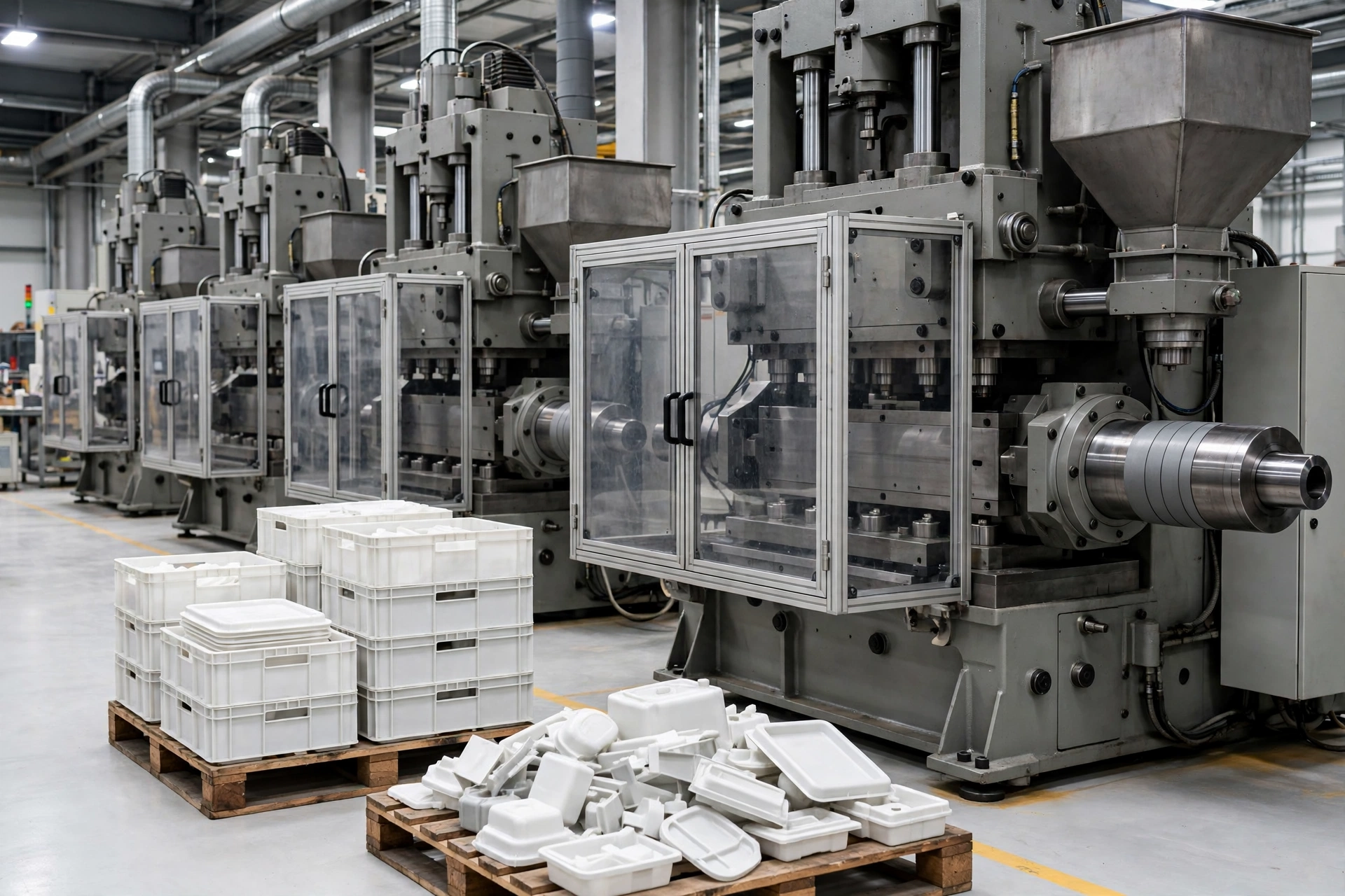
An injection moulding machine’s hydraulic pump is the load that catches buyers out, because it is not the largest motor on the nameplate but it is the one that peaks hardest. The pump reaches full load during injection and packing, and on a fixed-displacement machine it draws near-full power even with the mould open, dumping surplus oil through the relief valve as heat. A plant restarting after an outage must not start all its machines at once: the pumps will peak together, the voltage will dip, and the machines will fault on low voltage before they have made a single part. The restart sequence brings machines up in groups of three or four, with the barrel heaters already at temperature, and the first shots are run at reduced speed until the process stabilises. A servo-hydraulic or all-electric machine makes this easier — its pump follows demand, so the peak is lower and the restart is shorter — which is one more reason the drive type belongs in the generator sizing conversation.
Chillers and Air Compressors: Start Them First, Not Last
Chillers and air compressors are the loads most often left to last in a restart sequence, and they should be first. A chiller compressor of 75–110 kW starting direct-on-line draws 375–770 kW transient, and it must be running before the moulds can be held at temperature. An air compressor of similar size must be running before the ejectors and core pulls can move. The correct sequence is utilities first — chiller, compressed air, water pumps — then the extruders, then the injection machines in groups. A plant that starts the moulding machines first and the chillers last will make parts for ten minutes and then stop, because the moulds have warmed past their set temperature and the parts are out of tolerance. The ten minutes of production is wasted, and the machines must be purged again.
Fuel Autonomy: How Long the Set Has to Run
Fuel autonomy is the second half of the sizing question, and it is the half most often answered with a shrug. A set that runs for eight hours on its sub-base tank is no use in a ten-day outage, and a set with a 20,000-litre bulk tank is wasted capital on a site that loses power for two hours a year. The correct figure comes from the site’s outage history and the cost of a lost shift, not from the catalogue.
The fuel arithmetic is straightforward. A diesel generator consumes roughly 0.21–0.27 litres per kWh of electricity produced. The Cummins C500D5, rated 500 kVA standby / 455 kVA prime, consumes 93.2 L/h at full prime load — about 0.26 L/kWh. A 1,500 kVA set carrying 1,000 kW therefore burns about 250–260 L/h. The table below uses 0.25 L/kWh as a planning figure.
| Generator size | Load carried | Fuel use (L/h) | 8 hours | 24 hours | 72 hours |
|---|---|---|---|---|---|
| 500 kVA | 300 kW | 75 | 600 L | 1,800 L | 5,400 L |
| 1,000 kVA | 600 kW | 150 | 1,200 L | 3,600 L | 10,800 L |
| 1,500 kVA | 1,000 kW | 250 | 2,000 L | 6,000 L | 18,000 L |
| 2,500 kVA | 1,600 kW | 400 | 3,200 L | 9,600 L | 28,800 L |
| 5,000 kVA | 3,200 kW | 800 | 6,400 L | 19,200 L | 57,600 L |
A 72-hour autonomy at 1,500 kVA needs 18,000 litres — a bulk tank, not a sub-base tank, and a fuel delivery contract with a supplier who can reach the site during a regional outage. On the other side of the equation, diesel fuel ageing is the constraint: fuel stored for months without turnover grows water and microbes, and a bulk tank that is never used becomes a liability. The practical answer is a tank sized for the realistic outage — 24 hours for most sites, 72 hours for sites with a poor grid — with a fuel polishing and testing schedule that keeps the stock fresh. A plant that buys a 72-hour tank and never tests the fuel will find, on the day it matters, that the set stops after four hours on clogged filters.
Placement in a Hot, Dusty, Pellet-Filled Plant
A plastics plant is a hostile environment for a generator. The production hall runs hot, the air carries plastic dust and pellets, and the floor is washed down regularly. The set’s placement decides whether it starts on the day it is needed, and the three enemies are heat, dust and water.
Heat: The Hall Is Already at 35–40°C
A plastics production hall with extruders, moulding machines and chillers running at full load sits at 35–40°C even with ventilation, and higher near the extruder barrels. A generator rated at 25°C loses output as the temperature rises — the alternator loses about 3% per 10°C above 40°C, and the engine loses power as intake air density falls. A 1,500 kVA set in a 45°C hall is a 1,400 kVA set before it starts. The standard answer is to place the set outside the hall, in its own enclosure or a dedicated room, with its own ventilation. The generator room ventilation guide covers the airflow arithmetic: a 1,500 kVA set needs roughly 8–10 m³/s of cooling and combustion air, and a louvre sized for a 25°C hall will starve it in a 40°C one.
Dust and Pellets: The Radiator Problem
Plastic pellets are small, light and everywhere. They blow across the yard, they collect in corners, and they are drawn into any air intake in the area. A generator radiator clogged with pellets and plastic dust loses cooling capacity steadily, and the set that passed its monthly test in winter trips on high coolant temperature in summer. The same applies to the air filter: fine plastic dust loads it faster than ordinary industrial dust, and a choked filter costs power and fuel. The placement answer is distance and height — the set’s air intake at least 10 metres from the pellet handling area, and the radiator facing away from the prevailing wind that carries dust from the yard. The maintenance answer is a monthly radiator and filter check, on the diesel generator maintenance schedule, with the fins blown out rather than hosed, because wet plastic dust sets like concrete.
Water, Washdown and the Floor Drain
Plastics halls are washed down, and the wash water carries pellets, dust and sometimes oil. A generator set sitting on the hall floor, or in a pit, will stand in water sooner or later. The set belongs on a raised plinth, 150–200 mm above the finished floor, with its own drainage and with the fuel tank bunded separately. The electrical connections — the ATS, the distribution board and the generator control panel — belong above the washdown splash line, and the cable runs belong in sealed conduit, not in open tray at floor level. A set that has stood in wash water for a season will start, but its insulation resistance will have fallen, and the first damp morning will produce an earth fault that looks like a generator failure and is actually a placement failure.
Frequently Asked Questions
What size generator does a plastics plant need?
A small moulder with 5–10 machines typically needs 250–500 kVA for its essential board, a mid-size plant processing 3,000–10,000 tonnes a year needs 1,250–2,500 kVA, and a large film or packaging plant needs 2,500–5,000 kVA or parallel sets. The melt-critical lines — extrusion, the injection machines that stay on, and all utilities — decide the figure, not the total connected load.
Do plastics plants need a backup generator?
Any plant that runs melt continuously needs one, because the melt degrades after 5–10 minutes at full heat and a short outage costs a purge, a reheat and a restart on every machine. Plants on reliable grids with short outages can manage with a smaller set covering the essential board; plants on weak grids, or in regions with daily cuts of 2–3 hours, need prime-rated capacity and a fuel plan to match.
How long can a plastics plant run on a generator?
As long as the fuel lasts and the rating allows. A standby-rated set is limited to 200 hours a year under ISO 8528-1, so a plant that loses the grid for 300 hours a year needs a prime-rated set. On fuel, a 1,500 kVA set carrying 1,000 kW burns about 250 L/h, so a 6,000-litre tank gives 24 hours and an 18,000-litre bulk tank gives 72 hours.
What happens to a plastics plant during a power outage?
The barrel heaters stop, the melt inside every barrel and nozzle begins to degrade after 5–10 minutes, and the moulds cool. If power returns quickly and the heaters are banked down, the plant can restart with a purge of half the barrel capacity on each machine. If the melt has frozen in the barrel or the nozzles, the machines must be stripped, cleaned and reheated — a job measured in hours per machine, not minutes.
Can a diesel generator power a plastics plant?
Yes, and it is the standard answer for plants that cannot tolerate a melt freeze. The set carries the essential board — the melt-critical lines, the injection machines that stay on, chillers, compressed air and drying — while the rest of the plant is shed. A plant that needs its whole production floor on generator power, including every machine, will usually need parallel sets or a medium-voltage installation, and should be sized by a load list rather than by a rule of thumb.
Specification Checklist: Seven Lines Before the Deposit
1. Which rating is quoted — ESP, PRP or COP? The letters must appear on the datasheet and the contract. A plant that loses the grid for 300 hours a year needs prime, not standby, and the standby and prime power ratings decide whether the warranty stands.
2. What is on the essential board, in writing? The load list must name the lines that stay on, the machines that are shed, and the restart sequence. A quotation that prices from total connected load has not understood the plant.
3. What are the starting transients? Ask for the locked-rotor current of the largest extruder drive, the largest hydraulic pump and the largest chiller compressor, and for the soft starters or VFDs that limit them. A set sized on running load alone will trip on the first restart.
4. At what site conditions? Ask for the derated figure at the actual hall temperature and altitude, not the catalogue figure at 25°C and sea level. A set in a 45°C hall has already lost output before it starts.
5. How many hours of fuel, and how is it kept fresh? Ask for the tank size in litres, the autonomy at the essential-board load, and the fuel testing and polishing schedule. A 72-hour tank of stale fuel is a four-hour tank.
6. Where does the set sit? Ask for the plinth height, the distance from pellet handling, the radiator orientation and the ventilation airflow. A set that cannot breathe or that stands in wash water will fail on the day it is needed.
7. Will the warranty stand at the stated duty? Ask in writing: “If this set runs at the stated duty, for the stated annual hours, at the stated site conditions, will the warranty remain valid?” A direct answer, with the rating letters attached, is worth more than a 5% discount. A vague answer is a warning.
Before requesting a price, a buyer should provide four lines: annual output in tonnes and the process mix, the essential-board load list with the largest single motor and its starting method, honest annual outage hours including tests, and site temperature, altitude and enclosure type. Any manufacturer that knows its business — PAVO included, with a range of 9 to 3750 kVA in open, silent and containerised configurations, powered by Cummins, Weichai, Yuchai and Shanghai Diesel — will price the correct rating from those four lines. A supplier that prices from kVA alone is not doing the buyer a favour.
The melt does not wait for the grid to come back. It degrades in ten minutes, freezes in the barrel, and costs a purge and a restart on every machine it touches. The generator that keeps it moving through an outage is not an expense. It is the difference between a plant that loses an hour and a plant that loses a week. Size it on the melt, place it where it can breathe, and fuel it for the outage the site actually gets — then contact PAVO for a quotation sized to the plant, not to the catalogue.