

What Size Generator Does a Copper Smelter Need? | PAVO
A copper smelter does not stop when the power fails. It starts dying — one cooling pump, one furnace and one tankhouse at a time.
What size generator does a copper smelter need? A 300,000-tonne-a-year smelter needs 1,500–3,000 kVA on its critical board — furnace cooling, tankhouse, acid plant and utilities — not the 80–300 MW the furnaces draw. Size from the loads that must not stop, then add starting surge and fuel.
Contents
- Why a Copper Smelter Has No Pause Button
- The Smelter Process, Load by Load
- What Size Generator Does a Copper Smelter Need?
- What Happens When the Power Fails Mid-Shift
- How Long Can a Copper Smelter Run on a Generator?
- Power Quality, Rectifiers and the Generator
- Frequently Asked Questions
- Specification Checklist: Ten Lines Before the Deposit
Why a Copper Smelter Has No Pause Button
A copper smelter runs around the clock. Concentrate arrives by truck or rail, is dried, blown into a flash furnace at more than 1,250 °C, converted to blister copper, fire-refined into anodes, and then electro-refined into 99.99% pure cathodes in a tankhouse that never sleeps. A mid-size plant treats 200,000–300,000 tonnes of copper a year and draws 150–250 MW of electricity doing it. A fully integrated mine and smelter complex can exceed 600 MW of installed capacity.
Nothing in that chain has a pause button. A warehouse can wait out a blackout. A smelter cannot, because the product inside it is liquid metal at 1,200 °C, and liquid metal does not wait. It cools, it thickens, it solidifies, and every minute without power moves the plant closer to a restart measured in days or weeks rather than hours. The generator question for a smelter is therefore different from the generator question for almost any other factory. The set is not sized to keep the plant producing. It is sized to keep the plant alive while the grid is dead.
That distinction drives every number in this article. The furnaces draw tens or hundreds of megawatts. No diesel set backs them up, and no buyer should try. The generator backs up the loads that protect the furnaces, the tankhouse and the people: cooling water, gas cleaning, electrolyte circulation, cranes, hydraulics, controls and fire water. Those loads total a few megawatts at most — a scale a diesel set can carry. Getting that split right is the whole job.
The furnace clock
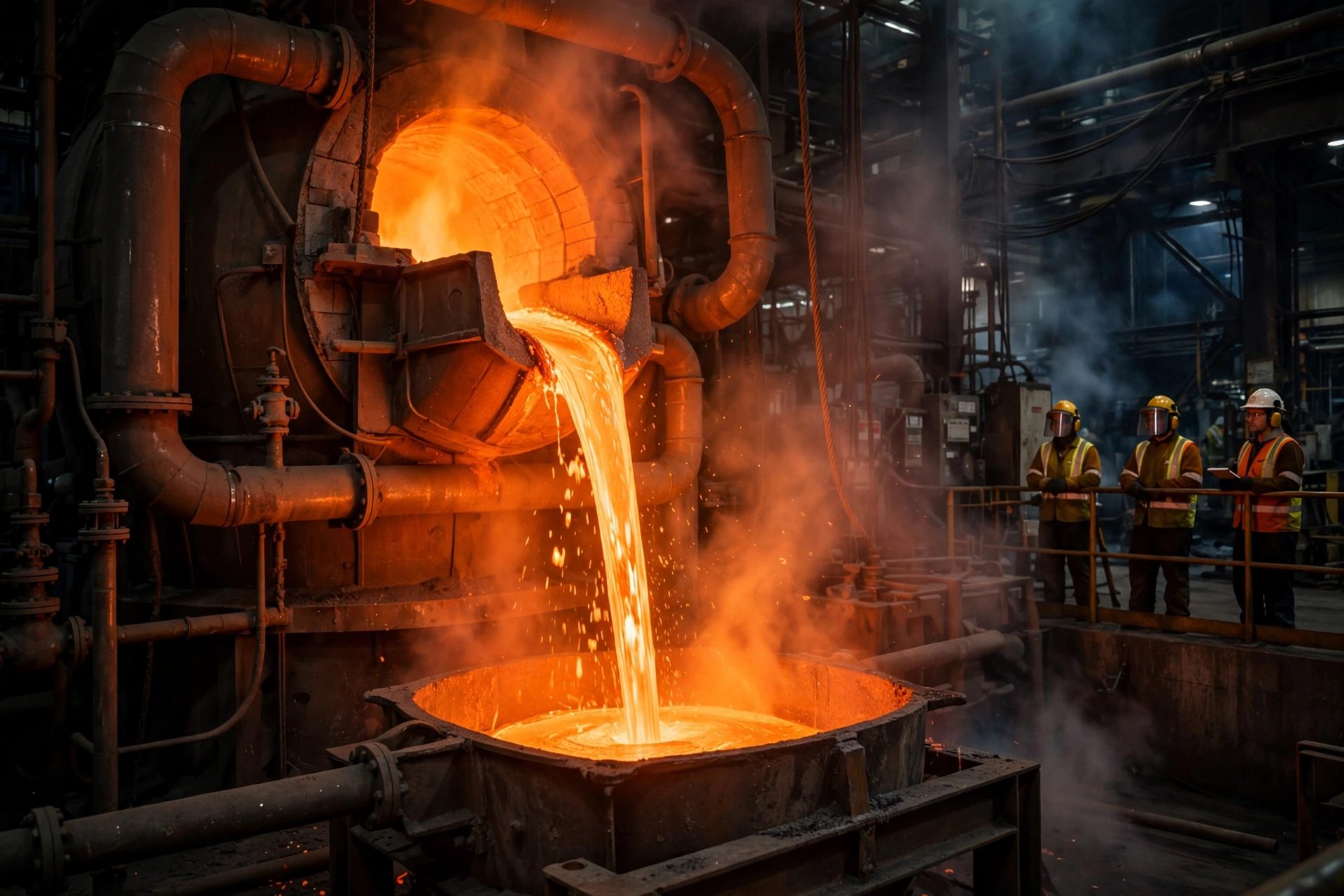
The furnace clock starts the second the power fails. A flash smelting furnace holds a bath of matte — molten copper-iron sulphide — at roughly 1,200 °C, tapped from the furnace in a glowing stream. Copper itself melts at 1,085 °C. The margin between a working furnace and a frozen one is therefore narrow, and it closes fast.
The first thing at risk is not the bath. It is the cooling water. Flash furnaces, converters and their off-gas systems are water-cooled, and the cooling circuit has a tolerable interruption measured in seconds, not minutes. Foundry practice — the same physics at a smaller scale — is explicit on this point: induction furnace coils and converter cooling that stop for more than a few minutes risk coil burnout, refractory damage and, in the worst case, a steam explosion where water meets molten metal. The standard defence is a second path that does not depend on the grid at all: an elevated header tank that gravity-feeds the cooling circuit through the generator start interval, or a diesel engine-driven pump that starts on its own.
The bath itself gives the crew more time, but not much. A furnace full of matte at 1,200 °C loses heat through its walls and roof from the moment the burners and oxygen stop. Within 2–4 hours the surface begins to skin over. Within 8–24 hours the bath stiffens enough that it can no longer be tapped or poured. Past that point the furnace is frozen: the charge has to be broken out mechanically, the refractory inspected and often partly replaced, and the furnace reheated over 1–2 weeks before it can take concentrate again. A flash furnace campaign normally runs for years between major rebuilds. One bad outage can end it early.
The tankhouse clock
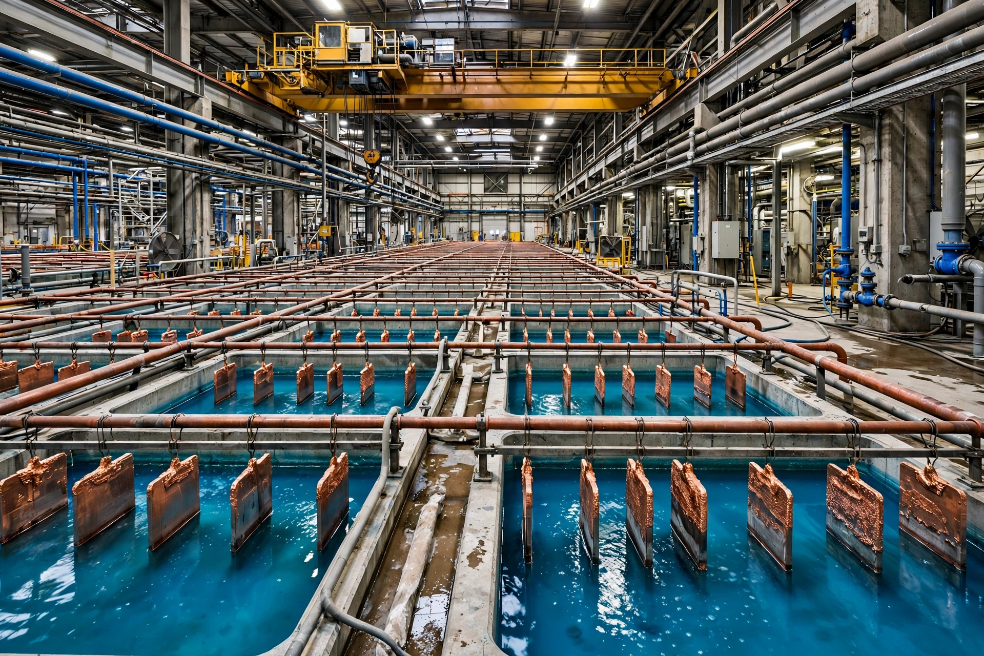
The tankhouse clock runs slower but the stakes are just as high. Electro-refining moves copper from an impure anode to a pure cathode through an acid electrolyte, cell by cell, at only 0.2–0.3 V per cell and about 250–300 kWh of DC per tonne of cathode. A large tankhouse holds thousands of tonnes of copper in process — anodes hanging in the cells, cathodes half-grown, electrolyte circulating at 60–65 °C.
A short stop is survivable. If the rectifiers trip for a few minutes, deposition pauses and resumes when current returns. The electrolyte stays warm, the chemistry stays stable, and the cathodes come out with a blemish at worst. A stop of several hours is a different event. The electrolyte cools, copper sulphate crystals begin to form, anodes passivate, and cathodes already in the cells grow unevenly. On restart, short circuits between anode and cathode are common, and every shorted cell has to be found and cleared by hand. Planned outages in electrorefining are handled by ramping the current down in a controlled way through an auxiliary rectifier at low current — a practice refined enough to be patented — precisely because a hard stop is so damaging. An unplanned blackout gives the tankhouse no such courtesy.
The Smelter Process, Load by Load
A smelter has five electrical stages. Two of them — the furnace and the tankhouse rectifiers — draw the overwhelming majority of the power and cannot be backed up by diesel. Three of them — gas cleaning, the oxygen plant and utilities — draw far less and must not stop. The table below shows the split for a typical 300,000-tonne-a-year smelter, then each stage is examined in turn.
| Stage | Typical load | Generator carries? | Tolerable gap |
|---|---|---|---|
| Flash furnace and converters | 80–300 MW (thermal + electric) | No — cooling, blowers, hydraulics only | Seconds for cooling water |
| Electro-refining tankhouse | 30–150 MW DC | No — pumps, crane, controls only | Minutes for current, hours for electrolyte |
| Acid plant and gas cleaning | 5–15 MW | Yes — blowers, pumps, fans | Minutes |
| Oxygen plant | 10–30 MW | Partial — auxiliaries and controls | Hours to restart if tripped |
| Utilities and life safety | 3–8 MW | Yes — cooling water, air, fire water, UPS | Seconds |
Flash furnace and converting
Flash smelting is the dominant modern route. Dried concentrate is blown with oxygen-enriched air into a reaction shaft, where the sulphide minerals ignite and melt in flight. The molten droplets fall into a settler, separating into matte and slag. The matte is tapped at about 1,200 °C and blown in a Peirce-Smith converter, where air oxidises the iron and sulphur out of it, leaving blister copper at 98.5–99.5% purity. The blister is fire-refined and cast into anodes.
The furnace and converter together account for most of the 80–300 MW a smelting stage draws, but that figure mixes thermal and electrical load: much of the heat comes from the oxidation of sulphur in the concentrate itself, not from the grid. The electrical load is in the auxiliaries — the oxygen and air blowers, the feed system, the cooling water pumps, the off-gas fans and the converter tilt hydraulics. Those auxiliaries are exactly what the generator must carry. A converter that cannot tilt cannot pour. A furnace whose cooling water stops cannot hold its bath. The melting load is not the generator’s job. Protecting it is.
Metso’s HSC-SIM modelling of the modern routes — Outotec flash smelting with flash converting, flash smelting with Peirce-Smith converting, Ausmelt top-submerged-lance smelting and converting, and the Mitsubishi process — used a 1.2-million-tonne-a-year concentrate feed as its base case. Every one of those routes is a continuous process. None of them tolerates an uncontrolled stop.
The electro-refining tankhouse
The tankhouse is the most power-quality-sensitive load on the site. Rectifiers feed direct current at 10–40 kA into rows of cells, each cell running at 0.2–0.3 V with a design point of about 0.285 V at 320 A/m² current density. A 21 kA rectifier line is a typical mid-size installation. The DC power itself — 30–150 MW for a large tankhouse — comes from the grid through transformers and rectifiers, and no diesel set replaces it.
What the generator does carry in the tankhouse is everything around the current: electrolyte circulation pumps, the overhead crane that moves anode and cathode plates, the ventilation that clears acid mist, and the control system that watches cell voltage for short circuits. The electrolyte pumps matter most. If circulation stops, the electrolyte stratifies, temperature falls unevenly across the tankhouse, and the cathodes already in the cells start to grow rough and nodular. A tankhouse that loses circulation for a few hours does not lose its copper. It loses days of cathode quality, and the rework is done cell by cell, by hand.
Acid plant and gas cleaning
A copper smelter is also a sulphuric acid plant. The off-gas from the flash furnace and converters carries 10–14% sulphur dioxide, and environmental permits require it to be captured, not vented. The gas passes through waste-heat boilers, electrostatic precipitators and a catalytic acid plant, emerging as concentrated sulphuric acid. A 300,000-tonne-a-year copper smelter produces roughly 1 million tonnes of acid a year — a by-product stream large enough to be a business in its own right.
The acid plant draws 5–15 MW, mostly in its main blower, acid circulation pumps and cooling. If the blower stops, the gas has nowhere to go: the furnace must be shut down or the gas vented, and venting sulphur dioxide is a permit breach with fines attached. If the acid pumps stop, hot acid sits in the towers and the catalyst beds cool unevenly, which can crack the catalyst support and cost weeks to repair. The acid plant is therefore on the critical board in full. It is also one of the few smelter loads where the generator must run continuously through a long outage rather than just through the restart sequence.
Oxygen plant and utilities
Flash smelting burns concentrate in oxygen-enriched air, and the oxygen comes from an air separation unit on site. A large smelter’s oxygen plant produces hundreds of tonnes of oxygen a day and draws 10–30 MW. The oxygen plant itself is too large for the generator, but its auxiliaries are not — and the trip behaviour matters more than the size. An air separation unit that trips takes 8–24 hours to return to full output, because the cold box has to be re-cooled and the distillation columns re-stabilised. A generator that keeps the oxygen plant’s controls, instrument air and cooling alive through a short outage can be the difference between a restart in hours and a restart the next day.
The utilities complete the critical board: cooling water pumps for the whole plant, compressed air for instruments and pneumatic valves, demineralised water, fire water pumps, emergency lighting and the control rooms, which run on UPS through the 10-second gap while the automatic transfer switch starts the set. None of these loads is large on its own. Together they are the reason the plant survives the night.
What Size Generator Does a Copper Smelter Need?
The sizing question has a trap in it. A buyer who sizes from the smelter’s total load ends up specifying a power station. A buyer who sizes from the critical board ends up with a generator set — or two, or three — that a factory can actually build, ship and maintain. The table below gives planning bands for the critical board by smelter capacity. They are bands, not a quotation: the exact figure comes from a load list, and the load list comes from the plant’s own electrical department. But the bands show the shape of the answer, and the shape surprises most first-time buyers.
| Smelter capacity (tpa Cu) | Total site load | Critical board | Generator size |
|---|---|---|---|
| 100,000 | 60–100 MW | 600–900 kVA | 800–1,200 kVA |
| 200,000 | 100–180 MW | 1,000–1,800 kVA | 1,250–2,000 kVA |
| 300,000 | 150–250 MW | 1,500–2,500 kVA | 1,500–3,000 kVA |
| 500,000 | 250–400 MW | 2,500–4,000 kVA | 3,000–5,000 kVA, 2–3 sets |
A 500,000-tonne-a-year smelter — the size of the Kamoa-Kakula plant now being heated up in the Democratic Republic of Congo — needs 3,000–5,000 kVA of emergency power, delivered as two or three sets in parallel rather than one giant machine. Two 2,000 kVA sets in parallel give redundancy: if one set fails to start, the other still carries the cooling water and the gas cleaning. One 4,000 kVA set does not. The generator sizing guide sets out the same logic for smaller plants, and it applies with more force here, because the cost of a failed start at a smelter is measured in furnace damage rather than inconvenience.
The critical board — what the generator actually carries
The critical board is a list, and it has to be built load by load with the plant’s engineers. The largest single item is usually the cooling water system: main circulation pumps of 200–500 kW each, with a standby pump that starts automatically if the duty pump trips. Next come the furnace and converter auxiliaries — tilt hydraulics, charging cranes, fume extraction fans — then the acid plant blower and pumps, the tankhouse electrolyte pumps and crane, the oxygen plant auxiliaries, and finally the site utilities: fire water, instrument air, lighting and the UPS that holds the control rooms through the transfer.
The starting sequence matters as much as the total. Cooling water pumps are large motors, and large motors start direct-on-line in most plants, drawing 5–7 times running current for a few seconds. The emergency-load logic is the same one used at steel mills, where the generator protects cooling water, cranes and controls rather than the arc furnace itself. If every critical motor starts at once, the generator sees a step load it cannot carry, the voltage dips, and the set trips on overload — exactly when the plant needs it most. The fix is staged starting: the automatic transfer switch brings the set up, the cooling water starts first, the acid plant blower second, the tankhouse pumps third, and the cranes and smaller loads last, each step separated by 10–20 seconds. That sequencing is written into the plant’s emergency procedure and tested on the monthly test run. The general rules for motor starting surges are covered in the companion article on motor starting, and the numbers there — locked-rotor current, voltage dip limits, soft-starter options — are the same numbers a smelter uses.
Standby, prime or continuous — which rating fits a smelter
Most smelters buy on the standby rating. The set waits, sometimes for months, then runs for the hours or days of a grid outage. The standby and prime ratings article explains the distinction in full: a standby-rated set is built for limited hours a year at varying load, while a prime-rated set is built for unlimited hours at variable load, and a continuous-rated set for constant load around the clock.
There are two cases where a smelter should buy prime instead. The first is a site on an unstable grid — parts of Zambia and the DRC, where copper smelters actually sit, see scheduled load shedding and unplanned outages running to hundreds of hours a year. A standby-rated set run for 1,000 hours a year will not last its design life, and the warranty will not cover it. The second is a smelter that uses the set for peak shaving or for scheduled maintenance cover, where the running hours stack up quietly. A 2,000 kVA set bought on standby rating and run for 800 hours a year is a warranty claim waiting to happen. Buy the rating that matches the hours, not the rating that matches the price.
Where the set sits
Placement at a smelter is harder than at most factories. The furnace building runs at 40–50 °C ambient near the roof, and a generator rated at 25 °C intake temperature loses roughly 1% of its output for every 5–6 °C above that — so a set sitting in 50 °C air is already down 4–5% before it takes a single kilowatt of load. The enclosure matters too: concentrate dust is fine, abrasive and conductive, and sulphur dioxide in the air corrodes unprotected steel. A standard canopy survives a warehouse yard. At a smelter it needs coated panels, sealed control cabinets and air filtration on the intake, or the set will be derating on a clogged radiator within a year.
Distance matters as well. The set should sit close enough to the critical board that cable runs stay short and voltage drop stays under 3%, but far enough from the furnace building that radiant heat and dust do not cook it. In practice that means a dedicated pad 50–100 metres from the furnace building, on a bunded concrete plinth, with the fuel tank beside it and the cable trench run underground. A set buried in the furnace building’s shadow is a set that fails its first real test.
What Happens When the Power Fails Mid-Shift
Three cases show what a power failure actually costs a smelter. Two are real, reported in the open. The third is the failure sequence every smelter plans against, hour by hour, because it is the sequence that turns a short outage into a frozen furnace.
Case 1 — Kamoa-Kakula, Democratic Republic of Congo
On 2 January, a fire damaged 36 MW of backup power at the Kamoa-Kakula copper complex in the Democratic Republic of Congo. The complex had recently installed 48 MW of onsite diesel-generated power, and its total backup capacity stood at about 190 MW before the fire. After it, the figure was 160 MW.
Nobody was injured and production operations were not affected. But the smelter team delayed the heat-up of the on-site copper smelter by up to three months. The smelter, once fully operational, is designed to produce an estimated 500,000 tonnes a year of 99.7%-pure copper anodes, with US$315 million of capital expenditure allocated to it in 2025 alone. The operator increased surveillance of the backup generators and placed dedicated fire crews at each bank of generators while engineers investigated.
The lesson is not that backup power failed. The remaining 160 MW was enough to run all of the complex’s operations except the smelter in the event of a total grid failure. The lesson is that the smelter — the single most valuable and most fragile asset on the site — was the load that could not be covered, and that a fire in the backup system itself delayed its commissioning by a quarter. Backup power is itself a system that needs protection, testing and separation. A generator bank that burns is worse than no generator bank, because it consumes the crew’s attention at the exact moment the plant needs it elsewhere.
Case 2 — Port Pirie and Olympic Dam, South Australia, 2016
On 28 September 2016, severe storms destroyed multiple 275 kV transmission lines and blacked out the entire state of South Australia. BHP’s Olympic Dam mine — one of the world’s largest copper deposits — suspended operations. Backup generators provided power to critical infrastructure and allowed a restart when power was restored, but copper production for the September quarter still fell 26% to 41,000 tonnes, and the site’s guidance of about 200,000 tonnes for the financial year went under review. Full ramp-up was not expected until the December quarter.
At Port Pirie, Nyrstar’s lead smelter fared worse. A backup diesel generator kept the blast furnace going, but the furnace still went down for 10–14 days for repairs. Slag had solidified inside it. The company put the loss at €3–5 million. The furnace was not frozen solid — the diesel had done its job — but the interruption was enough to damage the lining and force a repair outage measured in weeks.
Both cases carry the same message. The generator does not have to fail for the plant to lose money. It only has to be too small, too slow, or too late. A set that keeps the furnace alive but cannot keep the acid plant running, or a set that starts in 10 seconds when the cooling water needed it in five, still leaves the plant with a repair bill.
Case 3 — The furnace freeze, hour by hour
The sequence below is the one smelter engineers plan against. It is not a single incident. It is what the physics does, every time, when the critical board goes dark.
In the first 10 seconds, the automatic transfer switch senses the loss of mains, starts the generator and transfers the critical board. If the set starts cleanly, the cooling water never stops. If it does not start — flat batteries, empty day tank, a failed starter motor — the elevated header tank gravity-feeds the furnace cooling circuit for the 10–15 minutes it was designed to cover. That tank is the cheapest insurance in the plant, and the most commonly neglected: it is only useful if it is full, and it is only full if somebody checks it.
Between 10 minutes and 2 hours, the bath is cooling. The burners are out, the oxygen is off, and the furnace is losing heat through its walls at a rate the operators can watch on the thermocouples. The matte surface begins to skin over. The converters, which were mid-blow when the power failed, hold blister copper that is also cooling. The crew’s job in this window is triage: get the generator running, get the cooling water back, and decide whether to tap the furnace while it can still be tapped.
Between 2 and 8 hours, the skin thickens into a crust. The matte below it is still liquid, but it can no longer be poured cleanly. The tankhouse electrolyte has cooled below its working range and the rectifiers, if they restart now, will short across the cells. The acid plant catalyst beds are cooling unevenly. Every hour in this window adds a day to the restart.
Beyond 24 hours, the furnace is frozen. The charge has to be broken out mechanically, the refractory inspected course by course, and the furnace reheated over 1–2 weeks before it can take concentrate again. A frozen flash furnace is a US$5–20 million event depending on the size of the plant and the extent of the refractory damage — and it is the event the generator exists to prevent.
How Long Can a Copper Smelter Run on a Generator?
A smelter does not need the generator to run forever. It needs it to run long enough — long enough for the grid to return, or long enough for the plant to reach a safe state and shut down in an orderly way. Those are two different fuel numbers, and the plant should know both.
The fuel table below is built from a simple rule: a modern diesel set burns roughly 0.19–0.21 litres per kVA-hour at full prime load. The Cummins C500D5 datasheet gives the anchor point — 93.2 L/h at full prime load on a 455 kVA prime rating, 69.9 L/h at 75% and 49.0 L/h at 50%. The table scales that figure to the set sizes a smelter actually buys.
| Generator size | Full-load fuel use | 8 hours | 24 hours | 72 hours |
|---|---|---|---|---|
| 1,000 kVA | ~190 L/h | ~1,520 L | ~4,560 L | ~13,680 L |
| 1,500 kVA | ~285 L/h | ~2,280 L | ~6,840 L | ~20,520 L |
| 2,000 kVA | ~380 L/h | ~3,040 L | ~9,120 L | ~27,360 L |
| 3,000 kVA | ~570 L/h | ~4,560 L | ~13,680 L | ~41,040 L |
Fuel use at the critical board
The set rarely runs at full load. The critical board is sized with margin, and the running load through an outage is typically 60–75% of the set’s rating. At 70% load a 2,000 kVA set burns about 285 L/h, not 380 L/h — so a 24-hour outage costs roughly 6,800 litres, not 9,100. The difference matters when the fuel tank is being sized, because the tank is bought once and the outage that tests it may come in year five.
The day tank is the weak point. A 2,000 kVA set with a 1,000-litre day tank runs for less than four hours before the transfer pump has to refill it from the bulk tank — and if the transfer pump is not on the critical board, the set stops with a full bulk tank sitting 20 metres away. The transfer pump, its float switches and its own power supply belong on the emergency board, tested on every monthly run. The second weak point is diesel fuel ageing: fuel stored for a year in a hot smelter yard grows water and microbes, and a set that has not run for six months can fail on bad fuel at the exact moment it is needed. Polish the fuel, test it, and turn the stock over.
Autonomy — 8, 24 and 72 hours
Eight hours covers most grid faults. A transmission line trip, a substation fault, a storm that takes down a feeder — the utility usually restores supply within a working day, and 8 hours of fuel is enough to ride it out with the furnace protected and the tankhouse held. A 2,000 kVA set needs about 3,000 litres for eight hours at full load, less at part load.
Twenty-four hours covers a serious event: a storm that damages multiple lines, a substation fire, a regional blackout like South Australia in 2016. The plant needs roughly 7,000–14,000 litres depending on set size, which means a bulk tank rather than a day tank, and a fuel delivery contract that works on a weekend. A smelter that keeps 24 hours of fuel on site and has a supplier who answers the phone at 2 a.m. is a smelter that survives a regional outage.
Seventy-two hours is a different decision. Three days of fuel for a 2,000 kVA set is about 27,000 litres — a 30,000-litre bulk tank, bunded, permitted and filled. That is the autonomy a remote smelter buys when the nearest fuel depot is a day’s drive away, or when the grid is unreliable enough that outages are measured in days rather than hours. It is also the point where the fuel bill becomes a line item the finance department notices: 27,000 litres at roughly US$1 a litre is US$27,000 sitting in a tank, turning over slowly. The right autonomy is the one the plant’s own outage history justifies — and that history should be written down, not guessed.
Power Quality, Rectifiers and the Generator
A smelter is the hardest power-quality environment a generator will ever see, and the reason sits in the tankhouse. The rectifiers that feed the electrorefining cells are the largest non-linear load on the site, and they do not draw current the way a motor does. They draw it in pulses, and those pulses distort the voltage waveform for everything else on the bus — including the generator’s own alternator.
12-pulse rectifiers and harmonics
A six-pulse rectifier draws current in six chunks per cycle and injects characteristic harmonics — the 5th and 7th above all — back into the supply. Transformers, cables, switchgear and capacitor banks all have to carry that distortion, and the utility may charge for the power factor. A 12-pulse arrangement uses two bridges fed from secondaries displaced by 30 degrees, and the 5th and 7th harmonic currents cancel at the primary. The tankhouse still draws the same DC — a 21 kA line at 0.285 V per cell makes the same tonnes of cathode either way — but the AC side behaves itself.
The generator feels the difference. An alternator feeding a rectifier load needs a low subtransient reactance, or the voltage waveform distorts and the rectifier controls trip. The same rectifier problem appears at aluminium smelters, where potlines draw hundreds of kiloamps of DC through their own rectifiers. The established fix is oversizing: the companion guide on harmonics sets out a 2.5–3 times alternator oversizing rule for non-linear loads, and a smelter’s tankhouse is the case that rule was written for. A 1,500 kVA set feeding rectifier auxiliaries and control loads should carry an alternator sized as if it were a 3,000–4,000 kVA machine. The oversize costs money at purchase. It saves the plant from a rectifier trip in the middle of a restart, when the tankhouse is already fragile.
IEEE 519 sets the limits on harmonic distortion at the point of common coupling, and the smelter’s utility agreement will reference them. The generator’s own contribution to distortion is small compared with the rectifiers’, but the set has to live with the distortion the rectifiers create. Harmonic filters, a dedicated rectifier transformer with a 12-pulse secondary, and a generator alternator with a low reactance are the three pieces of the same answer.
Voltage dip, frequency and the UPS bridge
Motor starting is the second power-quality problem. When a 200–500 kW cooling water pump starts direct-on-line, it draws 5–7 times its running current, and the generator’s voltage dips 15–25% for a second or two. The rectifiers in the tankhouse are sensitive to that dip: their controls can trip on undervoltage, and a trip during a restart means the tankhouse goes dark again just as it was coming back. Staged starting — one large motor at a time, 10–20 seconds apart — keeps the dip inside the 10–15% the rectifiers tolerate, and soft starters on the largest pumps cut the dip further.
Frequency matters too. The generator’s governor holds 50 Hz or 60 Hz within a band, but a sudden step load drags the frequency down before the governor recovers. A 10% step load typically costs 1–2 Hz for a second; a 50% step can cost 3–4 Hz. The tankhouse controls and the plant’s PLCs ride through that on UPS, and the UPS is the bridge across the whole event: it holds the control rooms, the furnace instrumentation and the gas detection through the 10 seconds the automatic transfer switch needs to start the set and transfer the load. NFPA 110 sets the 10-second rule for emergency power to life-safety loads, and a smelter’s critical controls are treated the same way — because at a smelter, losing the controls is losing the plant.
Frequently Asked Questions
What size generator does a copper smelter need?
A 300,000-tonne-a-year smelter needs 1,500–3,000 kVA on its critical board, covering furnace cooling, tankhouse pumps, the acid plant and utilities. A 100,000-tonne plant needs 800–1,200 kVA, and a 500,000-tonne plant needs 3,000–5,000 kVA as two or three sets in parallel. Size from the critical board, not from the 80–300 MW the furnaces draw.
Do copper smelters need a backup generator?
Yes. A smelter’s furnaces hold molten metal at 1,200 °C, and a power failure that stops the cooling water can freeze a furnace within a day — a US$5–20 million event. The generator protects the cooling water, gas cleaning, tankhouse circulation and controls, not the melting load itself. No smelter with a flash furnace and a tankhouse should run without one.
How long can a copper smelter run on a generator?
As long as the fuel lasts. A 2,000 kVA set burns about 380 L/h at full load and about 285 L/h at 70% load, so a 10,000-litre bulk tank gives roughly 30 hours. Most smelters keep 24 hours of fuel on site and a delivery contract for longer outages; remote sites with unreliable grids keep 72 hours, about 27,000 litres for a 2,000 kVA set.
What happens to a copper smelter during a power outage?
The furnaces stop producing and the tankhouse stops refining, but the damage comes from what stops with them. Cooling water stops within seconds, the matte bath begins to skin over within 2–4 hours, and a furnace left without power for more than 24 hours can freeze solid, needing weeks of mechanical breakout and reheat. The acid plant stops capturing sulphur dioxide, and the tankhouse electrolyte cools and crystallises.
Can a diesel generator power a copper smelter?
It can power the parts that keep a smelter alive, not the parts that make copper. The furnace and tankhouse rectifiers draw 80–300 MW and 30–150 MW respectively — far beyond any diesel set. The generator carries the critical board: cooling water, gas cleaning, electrolyte pumps, cranes, hydraulics, controls and fire water, typically 1,500–3,000 kVA for a mid-size smelter.
Specification Checklist: Ten Lines Before the Deposit
- Critical board load list, signed by the plant’s electrical engineer — every load the generator must carry, with running and starting kW, and the starting sequence in writing.
- Set size from the critical board, not the site total — 1,500–3,000 kVA for a 300,000-tonne smelter, two or three sets in parallel above 3,000 kVA for redundancy.
- Rating matched to real running hours — standby for outage-only duty, prime if the grid sheds load for hundreds of hours a year, with the hours written into the order.
- Alternator oversized 2.5–3 times for rectifier loads — low subtransient reactance, 12-pulse rectifier transformer, harmonic filters where IEEE 519 limits apply.
- Automatic transfer switch with staged load starting — cooling water first, acid plant second, tankhouse third, 10–20 seconds between steps, tested monthly on the real loads.
- Cooling water second path — elevated header tank or diesel-driven pump that covers the generator start interval without any grid power.
- Fuel autonomy in writing — 24 hours on site as a minimum, 72 hours for remote sites, transfer pump on the critical board, fuel polished and tested.
- Placement and derating — set on a bunded plinth 50–100 metres from the furnace building, coated panels and filtered intake for dust and SO2, output derated for 50 °C ambient.
- FAT witnessed at the factory — full-load test, step-load test, voltage dip recorded, harmonic measurements with a rectifier load if the set will feed one.
- Service and spares in the contract — response time, spare AVR and starter motor held on site, and a named engineer who has seen a smelter before.
A copper smelter is the most unforgiving load a generator will ever protect. The furnace does not forgive a slow start, the tankhouse does not forgive a voltage dip, and the acid plant does not forgive a missed test. Size the set from the critical board, test it on the real loads, keep the fuel clean and the header tank full — and the next outage will be a story the crew tells over coffee, not a repair bill measured in millions. For a generator sized to a smelter’s critical board, with the rating, alternator and fuel autonomy the plant actually needs, contact PAVO for a specification and a quotation.