

What Size Generator Does an SMT Plant Need? | PAVO
In an electronics assembly plant, the grid does not fail at a convenient hour. It fails in the middle of a production run, with boards in the reflow oven and a shipment due the next morning.
What size generator does an SMT plant need? A single-line SMT plant typically needs a 150–250 kVA standby set, while a two-line plant needs 250–500 kVA and a four-line plant 500–1,000 kVA or more. The reflow oven’s cold-start surge, not the running load, usually decides the size.
- What an Electronics Assembly Plant Actually Loads
- The Reflow Window: Why the First Minutes Decide the Batch
- Sizing by Plant Size
- Three Plants That Lost Power — and What It Cost
- Fuel Autonomy: How Long an SMT Plant Can Run on a Generator
- Power Quality and Placement: Clean Power, Clean Air, ESD
- Frequently Asked Questions
- Specification Checklist
What an Electronics Assembly Plant Actually Loads
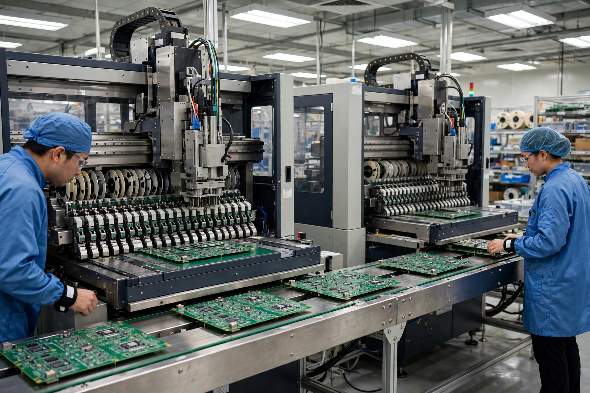
An electronics assembly plant’s electrical load looks nothing like a factory’s. There is no single big machine that dominates the bill. Instead the load is a stack of medium-sized machines and one large heating plant, and the heating plant is the part that cannot stop. A typical surface-mount technology (SMT) line runs a loader, a solder-paste printer, one or two pick-and-place machines, a reflow oven and an unloader, with inspection and test equipment downstream. None of these is large on its own. Together, with two or three lines running at once, the floor draws 150–400 kW at a mid-size plant.
The load is also unusual in a way that matters for generator sizing: most of it is resistive heating and precision electronics, not motors. The reflow oven is a bank of heaters. The pick-and-place machines are servo drives and vision systems. The test stations are computers. That mix is gentle on a generator in one respect — there are few large motor starts — and demanding in another: the load is sensitive to voltage and frequency in a way a pump or a fan never is. A voltage dip that a conveyor would ride through without noticing can reset a pick-and-place machine, drop a vision system and scrap the board it was working on.
The SMT line
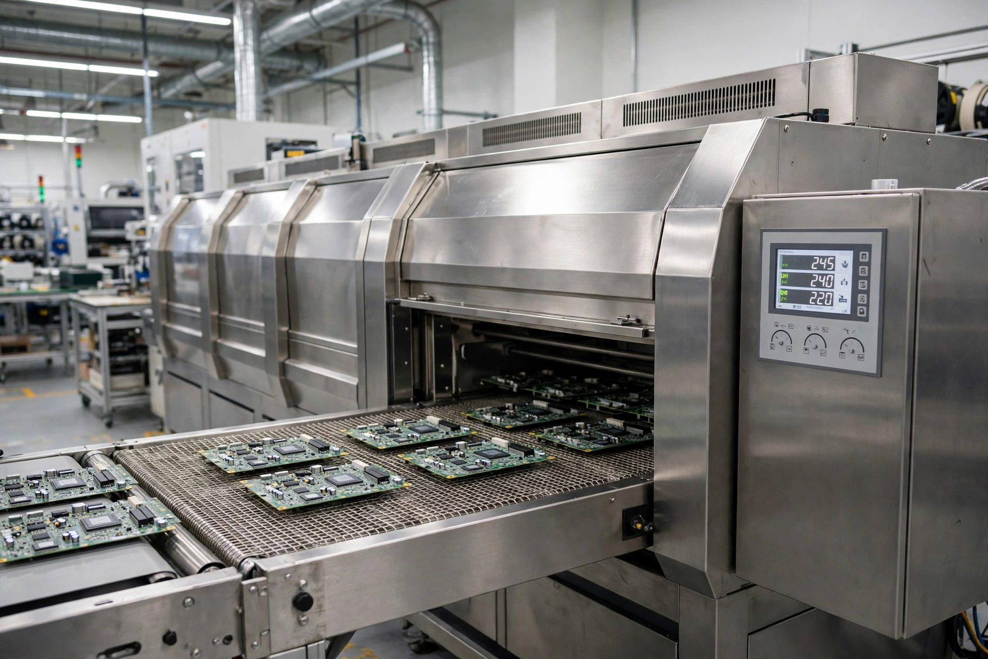
The SMT line is the heart of the plant, and its load is dominated by one machine. A 10-zone convection reflow oven draws 75 kW at cold start and 12–15 kW in normal running, according to the published specification of a common Chinese-built 10-zone oven. An 8-zone oven needs 55–64 kW to warm up and 8–12 kW once it is at temperature. A small 6-zone oven takes 28 kW total and runs on 4 kW. The pattern is the same at every size: the oven needs five to six times its running power to heat up, and it needs about 20–30 minutes to get there.
The rest of the line is small by comparison. A high-speed pick-and-place machine draws 2–3 kW. A solder-paste printer draws 220 W to 1 kW. Loaders, conveyors and unloaders draw 100–200 W each. A complete single line, oven included, runs on roughly 20–30 kW once it is warm, and needs 80–100 kW for the first half hour while the oven heats. That gap between starting load and running load is the single most important number in the whole sizing exercise, and it is the number most plant owners get wrong.
The line is also where the year’s work is most exposed. A mid-size plant running two lines at 25,000–35,000 components per hour per line produces 800–1,200 boards a day. If the power fails at midday with a line running and an order due the next morning, the boards in the oven are lost, the boards on the placement machines are half-populated, and the line needs an hour or more to recover even after the power returns. The loss is not the electricity. It is the boards, the schedule and the customer.
Wave and selective soldering
Not every board is pure SMT. Mixed-technology boards carry through-hole components — connectors, transformers, large electrolytic capacitors — that go through wave soldering or selective soldering after the SMT line. A wave soldering machine holds a bath of molten solder at 250–260°C, and it draws 10–20 kW to keep it there. A selective soldering station draws 5–8 kW.
The solder bath is a thermal load like the reflow oven, and it has the same weakness: it cools when the power stops, and it takes 30–60 minutes to come back to temperature. Worse, a bath that cools with dross and flux residue on the surface needs cleaning before it can run again. A plant that sizes its generator for the SMT lines and forgets the wave solder line discovers the omission the first time the power fails and the through-hole boards have nowhere to go.
Test and inspection
Test and inspection are small loads with an outsized consequence. Automated optical inspection (AOI) draws 1–2 kW per station. In-circuit test (ICT) draws 1–3 kW. A functional test rig draws 1–2 kW. Together a test area draws 5–15 kW, a rounding error next to the ovens. But these are the machines that decide whether a board ships. A board that was never tested cannot be sold, and a test sequence interrupted mid-run has to start again from the beginning. Test data is also the plant’s quality record: an interrupted test run leaves a gap in the traceability file that an automotive or medical customer will ask about at the next audit.
The test area is also where the plant’s computers live — the manufacturing execution system (MES), the line-control servers, the traceability database. These draw 2–5 kW between them, and they need clean power more than they need much power. A server that loses power mid-write corrupts a database. A server on a generator with poor frequency regulation reboots itself. Both failures look the same on the production floor: the line stops, and nobody knows which boards are good.
The utilities behind the line
The load that surprises first-time buyers is not on the production floor at all. It is in the plant room. An SMT plant runs on compressed air, and compressed air is electric. Pick-and-place nozzles, feeder actuators, stencil-printer squeegees and air knives all run on air at 0.5–0.7 MPa (5–7 bar). A mid-size plant’s screw compressor draws 22–37 kW, and a larger plant’s compressor draws 55–75 kW. A line with power but no compressed air is as idle as a line with no power at all, so the compressor has to be on the essential bus with the lines it serves.
Heating, ventilation and air conditioning is the second utility load. An SMT floor is held at 22–25°C and 40–60% relative humidity, year-round, and the air handling plant that holds it draws 20–60 kW depending on the size of the floor and the climate outside. The load is not comfort cooling. Solder paste has a working life measured in hours at room temperature, and its viscosity changes with temperature and humidity. A floor that warms up by five degrees changes the paste, changes the print and changes the yield. The reflow ovens also dump heat into the room: a 10-zone oven running at 12–15 kW puts most of that heat into the air around it, and the air conditioning has to remove it.
Nitrogen is the third utility, and it is the one most often forgotten. Lead-free reflow in a nitrogen atmosphere reduces oxidation and improves wetting, and many plants run their ovens on nitrogen at 500–2,000 ppm residual oxygen. The nitrogen comes from a pressure-swing adsorption (PSA) generator or from bulk liquid tanks, and the PSA unit draws 5–15 kW. A plant that sizes its generator for the ovens and forgets the nitrogen plant finds its reflow quality falling the first time it runs on diesel, because the ovens are running in air instead of nitrogen and the solder joints show it.
The Reflow Window: Why the First Minutes Decide the Batch
Reflow soldering is a live thermal process, and that is what makes a power cut in an electronics assembly plant different from a power cut anywhere else. When the power fails in a warehouse, the lights go out and the work stops. When the power fails in an SMT plant during a run, the ovens cool but the boards do not stop being half-soldered. The solder is part melted, the components are part placed, and the boards keep changing while nobody can do anything about it.
The numbers are unforgiving. Lead-free SAC305 solder melts at 217°C. A standard reflow profile takes a board from room temperature to a peak of 235–250°C over 3.5–5.5 minutes inside the oven, holding it above the liquidus for 45–90 seconds. That is the window in which every joint on the board forms. If the power fails while a board is in that window, the profile is broken and the board is scrap. There is no way to re-run a half-reflowed board: the paste has already melted, the flux has already burned off, and the components have already shifted.
What a reflow profile actually is
A reflow profile has four stages, and each one does a different job. Preheat takes the board from room temperature to about 150°C at 1–3°C per second, driving off solvents and evening out the temperature across the board. Soak holds the board at 150–180°C for 60–120 seconds, activating the flux and letting large and small components reach the same temperature. Reflow takes the board above 217°C to its peak, melting the solder and forming the joints. Cooling brings it back down at 2–4°C per second, freezing the joints in place.
| Profile stage | Temperature | Time in stage | What happens if power fails here |
|---|---|---|---|
| Preheat | 25–150°C | 60–90 seconds | Board cools slowly, paste survives, board can be re-run |
| Soak | 150–180°C | 60–120 seconds | Flux activates then stops, board usually scrapped |
| Reflow | 180–250°C peak | 45–90 seconds above liquidus | Solder half-melted, components shifted, board scrapped |
| Cooling | 250–25°C | 60–90 seconds | Joints freeze unevenly, cold joints and tombstoning |
The profile is controlled by the oven’s heaters and its conveyor, and both need power. Lose the heaters and the board cools inside the oven. Lose the conveyor and the board stops moving, sitting in one zone while that zone cools around it. Either way the board is lost. A 10-zone oven holds 8–12 boards inside it at any moment on a typical line, and every one of them is scrap after a power failure. At $50–$500 a board for populated assemblies, one outage costs $400–$6,000 in boards before anything else is counted.
What happens to a board mid-oven
The damage is not just the boards in the oven. Solder paste that has been printed and is waiting on the line has a working life of 4–8 hours at room temperature before it dries out and stops printing properly. Boards that were printed and are waiting to enter the oven go stale. Feeders loaded with components sit idle, and moisture-sensitive components — the MSD parts rated to IPC/JEDEC J-STD-033 — start their floor-life clock the moment their dry packs are opened. A power cut that lasts four hours does not just stop the line for four hours. It wastes the paste, wastes the printed boards and, in a humid climate, can push moisture-sensitive parts past their safe exposure time.
The placement machines suffer in a different way. A pick-and-place machine that loses power mid-cycle drops the component it was carrying, loses its vision calibration and forgets which feeder positions it had already used. Restarting it means re-homing the heads, re-checking the vision system and re-verifying the first boards off the line. That takes 30–60 minutes per machine, and it takes a trained operator, not a button press. A plant with four placement machines needs two hours of skilled work to get the floor running again after the power returns, and that is after the ovens have reheated.
The restart that costs more than the outage
The restart is where the real money goes. A reflow oven needs 20–30 minutes to heat up, and then it needs profiling: a test board run through the oven with thermocouples attached, to prove the profile is back inside specification. A plant that runs two or three different products a day needs a profile check for each one. The profiling alone takes 30–60 minutes per product, and a plant that skips it is shipping boards it cannot prove were soldered correctly.
Add it up and the shape of the loss becomes clear. A one-hour outage costs one hour of production, plus 30–60 minutes of oven heat-up, plus 30–60 minutes of profiling, plus 30–60 minutes per placement machine to re-home and re-verify. The line is down for three to four hours for every one hour the grid is down. That is why the downtime figures for electronics manufacturing are so large: the industry’s own numbers put mid-market electronics manufacturing downtime at $100,000–$500,000 per hour, and a Siemens and Senseye survey of manufacturers found that 82% of unplanned outages lasted an average of 4 hours and cost roughly $2 million per incident. Two-thirds of the plants surveyed had at least one unplanned outage every month. The generator does not just save the hour. It saves the three hours after it.
Sizing by Plant Size
Size the set from the oven cold-start load list, not the running load. The running load is a trap: it blends the ovens’ steady draw with the rest of the floor and produces a number that is too small for the only half hour that matters — the half hour when every oven on the floor is heating up at once. Work the numbers the way a generator sizing guide lays them out — running load first, then starting load, then a margin — and size for the minute when the ovens, the compressor and the air conditioning are all starting together.
| Plant size | Lines and output | Crush of cold-start load | Recommended standby set |
|---|---|---|---|
| Small, 1 line | 1 SMT line, 300–500 boards/day | 60–90 kW | 150–250 kVA |
| Medium, 2 lines | 2 SMT lines, 800–1,200 boards/day | 120–180 kW | 250–500 kVA |
| Large, 4 lines | 4 SMT lines, 2,000–3,000 boards/day | 250–400 kW | 500–1,000 kVA |
| Very large, 8 lines | 8 SMT lines, 5,000+ boards/day | 500–800 kW | 1,000–2,000 kVA, usually paralleled |
The table assumes the set carries the SMT lines, the test area, the compressor and the air conditioning, with the wave solder line and the nitrogen plant on the same bus. It does not assume the set carries the whole building: offices, the warehouse and the canteen stay on the grid side of the transfer switch. A plant that tries to carry everything buys a set twice the size it needs and then runs it at 30% load for its whole life, which is how wet stacking starts.
The oven cold-start trap
The trap is arithmetic. A 10-zone oven draws 75 kW to heat up and 12–15 kW to run. Four of them draw 300 kW to heat up and 50–60 kW to run. A generator sized from the running load — say 500 kVA for a four-line plant — sees a 300 kW step the moment the ovens are switched on together, on top of the 50–60 kW the lines are already drawing, plus the compressor start. The voltage dips, the frequency sags, and the generator’s protection trips. The ovens never reach temperature, and the plant has a generator that works perfectly on paper and fails on the floor.
There are three ways out, and a good project uses all three. First, sequence the oven starts: bring one oven up at a time, with 5–10 minutes between starts, so the generator never sees more than one cold-start step at once. Second, size the set for the largest single step, not for the sum of the running loads. Third, put the oven starts on the generator controller’s load-shed logic, so the ovens cannot all start together even if an operator tries. Sequencing alone can cut 100–150 kVA off the size of the set a four-line plant needs, which is the difference between a 500 kVA set and a 750 kVA set — roughly $15,000–$25,000 in purchase price, and a smaller fuel bill for the life of the plant.
Starting sequence — why order matters
The order in which loads come back matters as much as their size. The right sequence is: air conditioning and compressed air first, so the floor is cool and the pneumatics are live; then the test area and the servers, so the traceability system is recording before any board moves; then the placement machines, one line at a time; then the ovens, one at a time, with the profile check after each one. The wrong sequence is everything at once, which is what happens when the transfer switch closes and every contactor on the floor pulls in together.
A motor starting calculation still belongs in the sizing, even though the plant has few large motors. The air compressor is the largest motor on the floor — a 37 kW screw compressor draws 200–250 kVA for the first second on direct-on-line start, and a 75 kW compressor draws 400–500 kVA. The air conditioning fans and pumps add smaller steps. The sizing has to hold the voltage dip under 15% at the largest step, because the placement machines’ servo drives fault and the vision systems reboot at dips much deeper than that. A soft starter or a variable-frequency drive on the compressor cuts the starting step by two-thirds and is usually the cheapest kilovolt-amperes a plant can buy.
Three Plants That Lost Power — and What It Cost
The three cases below are drawn from the pattern every electronics manufacturer recognises: a short outage, a long recovery, and a bill that is larger than the outage itself. The numbers are the ones the industry publishes. Mid-market electronics manufacturing downtime runs $100,000–$500,000 per hour once scrap, rework, idle labour and penalties are counted, and a single hour of SMT stoppage costs $2,000–$5,000 in lost output before scrap and rework are added.
A two-line EMS plant in Shenzhen
A contract manufacturer in Shenzhen runs two SMT lines building control boards for home appliances, about 1,000 boards a day across two shifts. In the summer of 2025 the grid failed at 14:20 on a Tuesday, in the middle of a run of 400 boards for a single customer. The outage lasted 3 hours. The boards in the two ovens — 18 boards — were scrapped. The printed boards waiting on the line went stale and were cleaned and reprinted. The placement machines needed re-homing and re-verification, and the ovens needed 25 minutes to reheat and 40 minutes of profiling before the first good board came off the line.
The line was down for 6 hours for a 3-hour outage. The direct loss was 18 scrapped boards at $120 each, $2,160, plus 3 hours of idle labour for 24 operators at roughly $8 an hour loaded cost, $576. The real loss was the shipment: the 400-board order missed its truck, the customer imposed a $12,000 late-delivery penalty, and the plant paid $3,800 in air freight to get the replacement boards to the customer two days late. The total bill for a 3-hour outage was about $18,500. The plant bought a 400 kVA standby set six weeks later for roughly $38,000 installed. It paid for itself the next time the grid failed.
A six-line plant in Penang
A six-line plant in Penang builds automotive electronics — engine control units and sensor modules — for a customer whose contract allows zero late deliveries. In 2024 a substation fault cut power to the industrial park for 6 hours on a Friday afternoon. The plant had a generator, but it was sized for the offices and the warehouse, not the SMT floor. The lines stopped. The ovens cooled with 52 boards inside them. The nitrogen plant stopped, and the ovens ran their next shift in air until the nitrogen supply was restored.
Recovery took the weekend. The ovens needed profiling for 11 different products, and the test area had to re-run 300 boards whose test records were incomplete when the servers went down. The plant missed its Monday shipment of 2,400 units. The customer invoked the penalty clause: $45,000. The scrapped boards, the rework and the weekend overtime added $28,000. The plant’s management put the total at $73,000 for a 6-hour outage, and the figure does not include the audit finding that followed — the customer sent a quality auditor the next month, and the plant spent $15,000 on corrective actions to close the traceability gap. The plant now runs a 1,250 kVA set with the SMT floor on the essential bus, and the old office generator was sold.
A plant in Guadalajara whose generator tripped
A plant in Guadalajara bought a generator and still lost the line. The set was a 250 kVA unit, sized from the plant’s running load of 180 kW. The first time the grid failed, the transfer switch closed, the set took the load, and the operator switched on both reflow ovens together. The two ovens drew 150 kW between them to heat up, on top of the 180 kW already running. The generator’s voltage dipped past 20%, the frequency fell, and the set’s overcurrent protection tripped. The plant went dark a second time, ten seconds after the generator had saved it.
The fix cost almost nothing. The plant’s electrician added a start sequence to the generator controller: oven one starts 10 minutes after transfer, oven two starts 10 minutes after that, and the compressor starts first. The same 250 kVA set has carried the plant through four outages since, because it never sees more than one oven cold-start at a time. The lesson is the one this whole article keeps returning to: an SMT plant is not sized from its running load. It is sized from its largest single step, and the largest single step is almost always an oven heating up.
Fuel Autonomy: How Long an SMT Plant Can Run on a Generator
An SMT plant burns fuel slowly for the size of its load, because most of its load is resistive heating that runs at a steady draw once the ovens are warm. The number to plan around is the 75%-load figure, not the nameplate: a set rarely runs at full load, and a set that runs at 50–75% load is a set that will last. The table below uses a typical diesel consumption of about 0.21 litres per kWh at 75% load, and a 500 kVA set as the worked example — a Cummins C500D5, rated 500 kVA standby and 455 kVA prime. Those two numbers are the standby and prime ratings, and the gap between them is the margin that keeps the set alive on a long run. The C500D5 burns 93.2 litres per hour at full prime load and 69.9 litres per hour at 75%.
| Standby set | Load at 75% | Fuel use | 24-hour fuel | 72-hour fuel |
|---|---|---|---|---|
| 250 kVA | 150 kW | 35 L/h | 840 L | 2,520 L |
| 500 kVA | 300 kW | 70 L/h | 1,680 L | 5,040 L |
| 750 kVA | 450 kW | 105 L/h | 2,520 L | 7,560 L |
| 1,000 kVA | 600 kW | 140 L/h | 3,360 L | 10,080 L |
A 500 kVA set running a two-line plant for 24 hours needs 1,680 litres — a standard 2,000-litre sub-base tank with a margin. The same set for 72 hours needs 5,040 litres, which means a bulk tank or a fuel delivery contract. The fuel bill for a 24-hour run at 70 litres per hour is about $1,700 at $1.00 a litre. Set that against the $100,000–$500,000 an hour of downtime costs, and the fuel is not the expensive part of the decision.
The 24-hour number
Twenty-four hours is the right planning horizon for most SMT plants, because it covers the outages that actually happen: a substation fault, a storm, a feeder trip. The grid in most industrial areas is restored within a day, and a plant that can run for 24 hours can finish the shift, ship the order and hand over to the next shift with the line still running. A 2,000-litre tank on a 500 kVA set gives 28 hours at 75% load, which is the right size for a two-line plant. A 1,000-litre tank gives 14 hours, which is enough for the outage but not for the recovery — and the recovery, with its oven heat-up and profiling, is when the fuel is still being burned.
The mistake is to size the tank from the running load and forget the cold-start hour. The first hour on diesel burns 30–40% more fuel than the steady hours, because every oven on the floor is heating up at once. A plant that plans 1,680 litres for 24 hours and then heats four ovens from cold in the first hour has already burned 100 litres before the first good board comes off the line. Size the tank with a 20% margin over the table, and the margin will be used.
The 72-hour number
Seventy-two hours is the horizon for plants in areas with fragile grids, and for plants whose customers will not accept a missed shipment under any circumstances. A 500 kVA set needs 5,040 litres for 72 hours — a 6,000-litre bulk tank, or a 2,000-litre sub-base tank with a contracted delivery every 24 hours. The delivery contract is the part that fails most often: a fuel supplier that delivers in 48 hours on a normal day delivers in 72 hours during a storm, when every other plant in the industrial park is calling for fuel at the same time. A plant that plans for 72 hours of autonomy needs the fuel on site, not a phone number.
Fuel quality matters as much as quantity. The slow failure is diesel fuel ageing: diesel left in a standby set’s tank for a year grows water and microbes, and the first long run on old fuel is when the filters clog and the set stops. The fuel looks fine, the set starts fine, and then it stops four hours into the outage with a blocked filter. Test the fuel every 6 months, polish it once a year, and keep the tank full — a full tank grows less condensation than a half-empty one, and condensation is where the water comes from.
Power Quality and Placement: Clean Power, Clean Air, ESD
A generator makes power. It does not make clean power, and an SMT plant needs clean power. The difference is the reason so many electronics plants pair their generator with a UPS, and the reason the pairing has to be designed rather than assumed. A generator and a UPS that have never been tested together are two separate promises, and the plant discovers which one breaks first during the first real outage.
The generator is not a UPS
The gap is time. An automatic transfer switch takes 10 seconds to detect the failure, start the generator and transfer the load, and the generator’s first seconds are electrically rough: cranking, firing, ramping to speed, the voltage regulator hunting for the right voltage, the governor hunting for the right frequency. An SMT line cannot ride through 10 seconds of nothing, and it cannot ride through the rough first seconds either. The pick-and-place machines reset, the vision systems reboot, and the boards in the oven start cooling.
The UPS covers the gap. A double-conversion UPS sits between the generator and the critical loads, delivering a clean sine wave no matter what the generator or the grid is doing, and its battery carries the line for the 10–30 minutes it takes the generator to stabilise. The approach mirrors the one used for semiconductor fabs, where the industry wrote its own version of this requirement as SEMI F47: process tools must ride through voltage sags down to about 50% of nominal voltage for around 200 milliseconds. SMT equipment is not built to SEMI F47, but the principle is the same — the tools need a ride-through the generator cannot give them on its own, and the UPS is what provides it.
The pairing needs one design decision that is often missed: the UPS and the generator have to agree on frequency. A UPS that sees the generator’s frequency wandering during load steps will keep switching to battery, and a UPS on battery drains its batteries and then drops the load. UPS switching to battery on generator power is the most common generator-UPS failure in electronics plants, and it is fixed by sizing the generator with enough margin that its frequency stays inside the UPS’s acceptance window — typically ±2–3 Hz — at the largest load step. A generator sized with 25% margin over the running load usually holds frequency well enough. A generator sized with no margin does not.
Harmonics and the VFD problem
The second power-quality problem is harmonics. An SMT floor is full of non-linear loads: variable-frequency drives on the air conditioning fans and the compressor, switch-mode power supplies in the test equipment, servo drives in the placement machines. Each one draws current in pulses rather than in a smooth sine wave, and the pulses add up to harmonic distortion on the generator’s output. The alternator sees a distorted waveform, runs hotter, and delivers less usable power than its nameplate suggests.
The rule the industry uses is simple: size the alternator at 2.5–3 times the non-linear load, or fit harmonic filters on the largest drives. A 75 kW compressor on a variable-frequency drive needs an alternator sized as if it were a 190–225 kW load, unless the drive has a harmonic filter. A plant that sizes its generator from the kilowatt total and ignores the harmonics buys a set that overheats its alternator and trips on a hot day. The same harmonics that distort the waveform also disturb the UPS, which is another reason the generator needs margin: the margin is not waste. It is the space the harmonics live in.
ESD, dust and where the set sits
An SMT plant is an electrostatic-discharge (ESD) controlled area, and the generator installation has to respect that. The floor is held to IEC 61340-5-1, with grounded workstations, wrist straps and conductive flooring, and the generator’s own earthing has to tie into the same system without creating ground loops. A generator earthed to a separate rod, twenty metres from the plant’s earth, creates a potential difference between the two earths, and a potential difference is what damages components. Bond the generator to the plant’s main earth bar, test the bond, and write the reading down.
Dust is the second placement problem. An SMT floor is typically held to ISO 14644 Class 8 — 3,520,000 particles of 0.5 micron and larger per cubic metre — which is not a semiconductor cleanroom but is far cleaner than a warehouse. The generator’s radiator fan moves 10,000–20,000 cubic metres of air an hour, and if the set sits upwind of the plant’s air intake, it blows exhaust and dust straight into the air handling plant. Put the set downwind, keep 10 metres between the exhaust and the nearest intake, and fit the set with a hospital-grade silencer if the plant is near housing — a 500 kVA set in a standard canopy measures about 75 dB(A) at 7 metres, and a hospital-grade silencer takes 10–15 dB(A) off that.
Heat is the third placement problem, and it is the one that bites in summer. A 500 kVA set rejects roughly 150 kW of heat into its radiator air, and in a 40°C climate that air has to go somewhere. A set in a room with louvres sized for a temperate climate derates in a hot one: a generator rated at 25°C loses about 1% of its output for every 5–6°C above 40°C at the radiator inlet, and a room that recirculates its own hot air can cost the set 10–15% of its rating on the hottest day of the year. Size the louvres for the hottest day, not the average day, and put a temperature sensor in the room that alarms before the set derates.
Frequently Asked Questions
What size generator does an SMT plant need?
A single-line SMT plant typically needs a 150–250 kVA standby set, a two-line plant needs 250–500 kVA, and a four-line plant needs 500–1,000 kVA. The reflow oven’s cold-start surge decides the size: a 10-zone oven draws 75 kW to heat up and only 12–15 kW to run, so sequence the oven starts and size for the largest single step.
Do electronics factories need a backup generator?
Yes, if they run SMT lines. A power cut scraps the boards in the reflow oven, wastes printed boards and solder paste, and costs 3–4 hours of recovery for every 1 hour the grid is down. Mid-market electronics manufacturing downtime runs $100,000–$500,000 per hour once scrap, rework and penalties are counted, so a generator pays for itself in a single outage at most plants.
How long can an electronics plant run on a generator?
As long as it has fuel. A 500 kVA set running a two-line plant burns about 70 litres per hour at 75% load, so a 2,000-litre tank gives roughly 28 hours and a 6,000-litre bulk tank gives roughly 72 hours. Plan for 24 hours as a minimum, and keep the fuel on site rather than relying on a delivery during a storm.
What happens to an SMT line during a power outage?
The boards inside the reflow oven are scrapped, because the solder profile breaks mid-cycle and a half-reflowed board cannot be re-run. The pick-and-place machines drop their components, lose vision calibration and need 30–60 minutes each to re-home and re-verify. The ovens then need 20–30 minutes to reheat and 30–60 minutes of profiling before the first good board comes off the line.
Can a diesel generator power an electronics assembly plant?
Yes, with two conditions. First, the set must be sized for the reflow ovens’ cold-start surge and sequenced so the ovens never start together. Second, it must be paired with a double-conversion UPS that covers the 10-second transfer gap and the generator’s rough first seconds, because SMT controls cannot ride through a voltage dip the way a pump or a fan can.
Specification Checklist
- Size the set from the oven cold-start load list, not the running load, and sequence the oven starts with 5–10 minutes between them.
- Rate the set on standby duty with a 25% margin over the running load, so the frequency stays inside the UPS acceptance window at the largest step.
- Put the SMT lines, the test area, the compressor, the air conditioning and the nitrogen plant on the essential bus, and leave offices and the warehouse on the grid side.
- Fit an automatic transfer switch with a 10-second transfer target, and test the full transfer monthly under load.
- Size the fuel tank for 24 hours at 75% load as a minimum, with a 20% margin for the cold-start hour, and test and polish the fuel every 6 months.
- Pair the generator with a double-conversion UPS sized for 10–30 minutes of battery, and test the generator and the UPS together under load, not separately.
- Check the alternator against the harmonics from variable-frequency drives and switch-mode supplies, and fit filters or oversize the alternator where the non-linear load is large.
- Bond the generator to the plant’s main earth bar for ESD control, keep 10 metres between the exhaust and the nearest air intake, and size the room louvres for the hottest day of the year.
- Keep a maintenance schedule with oil, filters and coolant on hours and on calendar, and a remote monitoring link so the set’s alarms reach the maintenance team wherever they are.
- Keep a rental contact for a second set before the busy season, because the week the grid fails twice is the week a single set is being serviced.
For a generator sized to your SMT lines, your ovens and your fuel autonomy, contact PAVO with your line count, your oven sizes and your shift pattern, and PAVO will size the set, the tank and the transfer switch for your plant.