

What Size Generator Does a Hydroelectric Plant Need? | PAVO
A hydroelectric plant makes its own power — until the grid fails, the turbines stop, and the gates that hold back the reservoir cannot move.
What size generator does a hydroelectric plant need? A 5–25 MW run-of-river plant typically needs a 100–150 kVA set, a 50–300 MW station needs 500–1,500 kVA, and a 1,000 MW-plus plant needs 1,000–2,000 kVA across two or more sets. The set powers gates, governors and station service — never the turbines’ megawatt output.
- A Power Plant That Cannot Power Itself
- What a Hydroelectric Plant Actually Needs Power For
- The Gate That Cannot Move: Oroville, February 2017
- Sizing the Set: Three Plant Sizes
- Black Start: The Hydro Plant’s Second Job
- Fuel, Placement and the Dam-Site Problem
- Frequently Asked Questions
- Specification Checklist
A Power Plant That Cannot Power Itself
A hydroelectric plant is the one power station that seems immune to a blackout. The river keeps flowing, the reservoir sits full behind the dam, and the turbines are the machines that make the electricity. A buyer looking at a 280 MW station on paper sees a plant that generates its own power and assumes it can look after itself. That assumption is wrong in the one situation that matters most.
When the grid fails, a hydroelectric unit trips. The generator breaker opens, the governor closes the wicket gates, and the turbine spins down. The plant’s own output disappears in seconds, and with it goes the station service supply that the plant draws from its own generator terminals or from the grid connection. What remains is a dam full of water, a powerhouse full of stopped machines, and a list of loads that still need power: the gates that control the reservoir, the oil pumps that hold the turbine bearings, the excitation system, the battery chargers, the control room, the drainage pumps that keep the powerhouse dry.
The world’s largest hydroelectric plant states the point in its own design. The Three Gorges Dam in China is rated at 22,500 MW, with 32 main turbines of 700 MW each. It also has two 50 MW units whose job is to power the plant itself. Even a station that can light a country keeps dedicated house generation, because the megawatt machines cannot be counted on to power their own auxiliaries when the grid is gone.
That is the sizing question in its honest form. Nobody buys a diesel generator to run a hydroelectric turbine. The set exists to keep the dam safe, the machines restartable, and the station’s own loads alive while the grid is down. A 500 kVA set on a 280 MW station looks absurd until the arithmetic is done: the station’s critical auxiliary load is about 310 kW, and the set that covers it is the difference between a controlled shutdown and a dam that cannot move its gates.
The cost of getting this wrong is not measured in lost generation. Lost generation is priced in megawatt-hours and recovered when the grid returns. The cost is measured in water that cannot be released, a reservoir that keeps rising, a turbine bearing that runs dry, or a grid that waits hours longer for its fastest black-start resource. This article sizes the set for three classes of hydroelectric plant, explains what each load actually draws, and works through the two cases every dam engineer knows: Oroville in 2017, and the blackout of 2003.
What a Hydroelectric Plant Actually Needs Power For
A hydroelectric plant’s auxiliary load falls into three tiers, and the tiers decide the set size, the redundancy, and the starting sequence. The tiers are not equal in urgency. The first tier keeps the dam safe. The second tier keeps the machines restartable. The third tier keeps the people and the building working. A set that covers all three is sized for the first two; the third is shed first when fuel runs short.
The US Army Corps of Engineers states the design rule in its electrical design manual for hydroelectric plants, EM 1110-2-3006: the station service system should have a minimum of two full-capacity, redundant power sources, and the loss of one source must never leave the plant without service power. A diesel generator is the second source at most plants. The manual also defines black start as the ability of the plant, without any external source of power, to maintain itself internally, start its generating units, bring them to speed-no-load conditions, close the generator breakers, energise transformers and transmission lines, and hold the units while the rest of the grid is re-established.
Spillway Gates and Intake Screens
The first tier is water control. Spillway gates, intake gates, draft-tube gates and trash-rack cleaners all need power to move, and they need it precisely when the plant has lost its normal supply — during a storm, a flood, or a grid failure that coincides with high inflow. A gate that cannot open cannot release water. A gate that cannot close cannot stop it.
Gate drives are usually hydraulic power units or electric hoists. On a medium station the intake gate hydraulic unit draws around 90 kW, and it is the largest single motor start in the auxiliary load list. On a large dam the radial gates are driven by individual hoists of 30–75 kW each, and the gates must be moved one at a time, in sequence, so the set never sees all of them starting together. The load is intermittent — a gate moves for minutes, then stops — but it is non-negotiable. A station that cannot operate its spillway gates during a flood is a dam safety incident, not a generation outage.
Intake screens and trash racks belong in the same tier. A rack clogged with debris starves the turbine of water and trips the unit on low flow. The rake or travelling screen that clears it draws 10–25 kW and runs for a few minutes at a time. It is a small load with an outsized consequence: a blocked intake during a black start attempt leaves the unit unable to load.
Governor, Excitation and Unit Auxiliaries
The second tier is the machinery that lets a stopped unit start again. A Francis or Kaplan turbine does not restart by itself. The governor oil pressure unit must build pressure before the wicket gates can open. The bearing oil pumps must be running before the shaft turns. The cooling water pumps must be running before the unit loads. The excitation system must have power to flash the field.
On a 280 MW station with three 93 MW Francis units, these loads add up to roughly 200 kW: governor oil pumps 55 kW, turbine bearing cooling water pumps 75 kW, generator hydrogen cooling 30 kW, excitation system 20 kW, and DC battery chargers 15 kW. None of them is large on its own. Together they are the reason a hydroelectric plant cannot black-start itself from a battery alone, and the reason the diesel set is sized in hundreds of kVA rather than tens.
The governor deserves particular attention. A modern electro-hydraulic governor holds the unit at synchronous speed by adjusting the wicket gates several times a second. It needs oil pressure at 60–80 bar and a continuous supply of clean, cool oil. If the oil pumps stop, the governor accumulates pressure from its accumulator for a few minutes and then the unit trips. The pumps are therefore on the essential bus, and the set must start them within seconds of a station service failure, not minutes.
Station Service and the Control Room
The third tier is everything else that keeps the station habitable and operable: the control room and its SCADA servers, communications, lighting, ventilation, the powerhouse overhead crane, drainage and dewatering pumps, fire protection pumps, and the workshop. The dewatering pumps that keep a powerhouse dry are the same duty as water and wastewater treatment plant pumps, and they start against a flooded sump with a locked-rotor transient to match. The control room alone draws 20–30 kW — servers, screens, radios and the battery chargers that keep the 125 V DC system alive.
The DC system is the plant’s last line of defence. Protection relays, breaker trip and close coils, governor controls and emergency lighting all run on 125 V DC from the station battery. The battery is sized for 8 hours of autonomy under IEEE 485, and the diesel set’s job includes recharging it. A battery that is allowed to run flat leaves the plant with no protection at all: breakers that cannot trip, relays that cannot see a fault, and a control room that goes dark. The Lower Monumental Dam project on the Columbia River lists the same critical loads for its station service upgrade: spillway control, fish passage systems, drainage, unwatering pumps, and the DC system that ties them together.
The three tiers together explain why a hydroelectric plant’s diesel set is sized the way it is. The total is small against the plant’s megawatt rating — a fraction of one percent — and large against anything a site would call a small generator. That ratio is the first thing to get right in the specification.
The Gate That Cannot Move: Oroville, February 2017
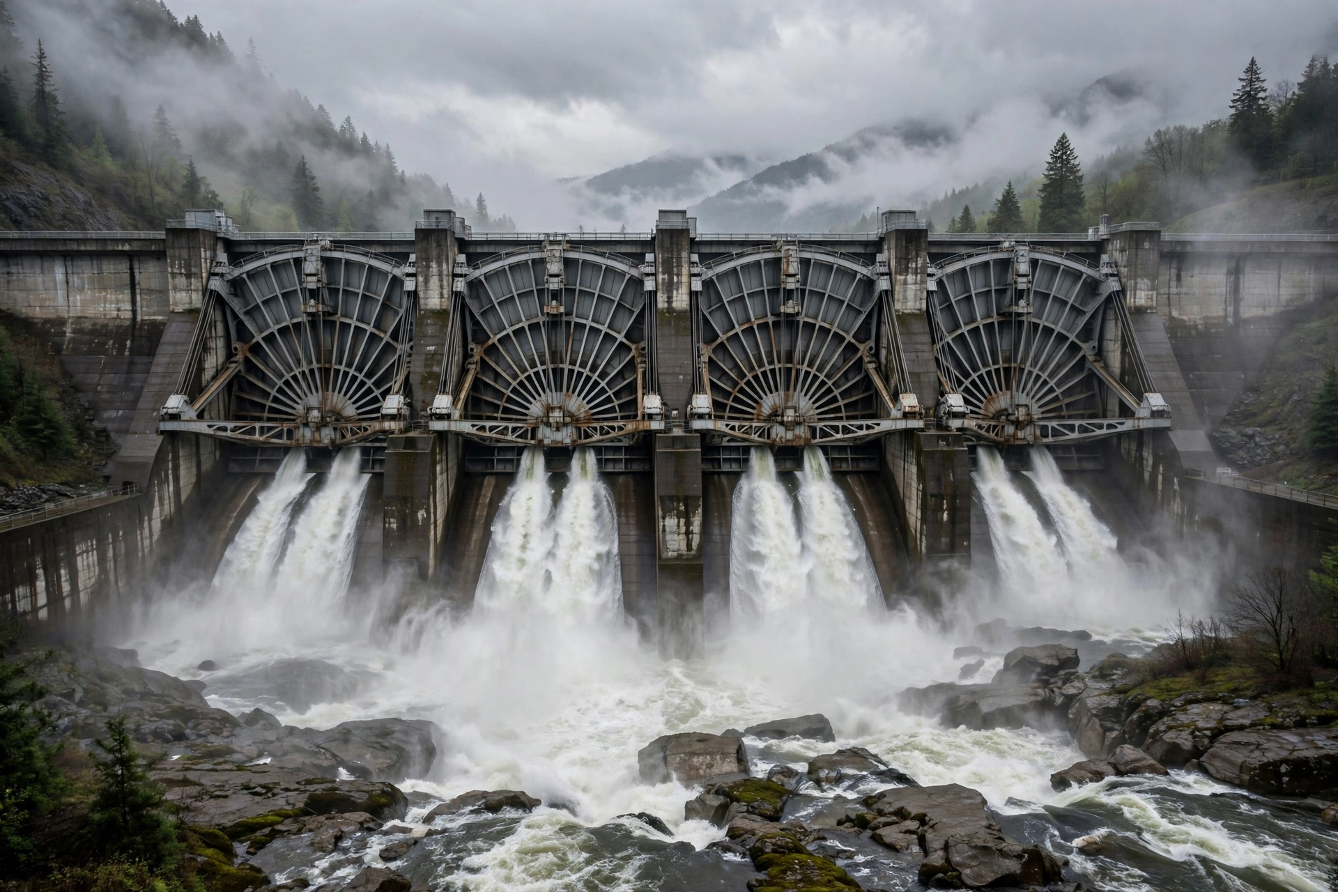
No case states the gate problem more clearly than Oroville Dam in California, in February 2017. Oroville is the tallest dam in the United States at 235 metres, completed in 1968, impounding Lake Oroville — the second-largest reservoir in California — and supplying water to 27 million people and 750,000 acres of farmland through the State Water Project. Its powerhouse holds 800 MW of generating capacity, including pumped storage. Its main spillway, the Flood Control Outlet, is a concrete chute 55 metres wide and nearly a kilometre long, controlled by eight radial gates, with a design discharge of 296,000 cubic feet per second.
The Week the Lake Rose 50 Feet
Early February 2017 was one of the wettest winters in northern California’s history. Atmospheric river storms filled the Feather River watershed, and within days Lake Oroville rose more than 50 feet, with inflows exceeding 130,000 cubic feet per second. Operators opened the spillway gates to release the excess. On 7 February, while discharging 52,500 cubic feet per second — well below the spillway’s design limit — they noticed an unusual flow pattern halfway down the chute and closed the gates to inspect. A section of concrete slab had lifted out, and the ground beneath it had washed away.
With the main spillway damaged, operators restricted flows while the lake kept rising. On 11 February the lake passed 901 feet and water crossed the emergency spillway crest — a concrete weir with an unlined hillside below it — for the first time in the dam’s history. The overflow eroded the hillside fast, cutting back toward the crest itself. At 3:44 pm on 12 February, about 188,000 people downstream were ordered to evacuate. The rebuild that followed cost an estimated $1.1 billion.
The 55 kW Generator That Was in the Manual
The spillway failure was a concrete and foundation problem, and the forensic investigation ran to 600 pages on that subject. But the crisis exposed a second, quieter failure that the investigation did not discuss: the power supply to the spillway gates. In a legislative oversight hearing in January 2018, California Department of Water Resources officials admitted that the department could have lost control of the spillway radial gates for days during the crisis if crucial power lines had gone down.
The department’s own Bulletin 200, published in 1974, specified a standby power source for the gates: a 55 kW generator driven by a liquid-propane-gas-fuelled engine. It was not available during the crisis. The groups that petitioned the Federal Energy Regulatory Commission — Friends of the River, the Sierra Club, the South Yuba River Citizens League and others — asked the commission to require the department to explain why the backup supply was unavailable, and to require an accessible electrical supply for the radial gates. Their point was simple: the gates are the dam’s only way to control the reservoir, and the power that moves them cannot depend on the same lines that a storm is taking down.
A 55 kW set is a small generator. It would fit in a single canopy on the dam crest. It would have cost a fraction of one percent of the $1.1 billion rebuild. Its absence did not cause the spillway failure, but it meant that during the most dangerous week in the dam’s history, the operators’ control of the reservoir depended on power lines running through the same storm that was filling the lake. That is the arithmetic every hydroelectric plant should do before the storm, not after it.
What a Gate Hoist Actually Draws
The Oroville lesson is a sizing lesson as much as a planning lesson. A radial gate hoist motor is typically 30–75 kW, and it starts direct-on-line with a locked-rotor current five to six times its running current. A set that is sized only for the gates’ running load will dip its voltage on the first start, and the motor starting transient will stall the hoist or trip the set’s own protection. The set must be sized for the starting kilovolt-amperes, not the running kilowatts, and the gates must be sequenced one at a time.
The same rule applies to the intake gate hydraulic power unit, which at 90 kW is usually the largest single start in the station service load. On the Nam Ou 7 station in Laos, the intake gate unit draws 540 kW of inrush for half a second — the largest single transient in the whole auxiliary load list. A set that cannot absorb that transient cannot open the intake gate, and a unit that cannot open its intake gate cannot start. The gate is the first load in the black-start sequence and the last load that can be allowed to fail.
Sizing the Set: Three Plant Sizes
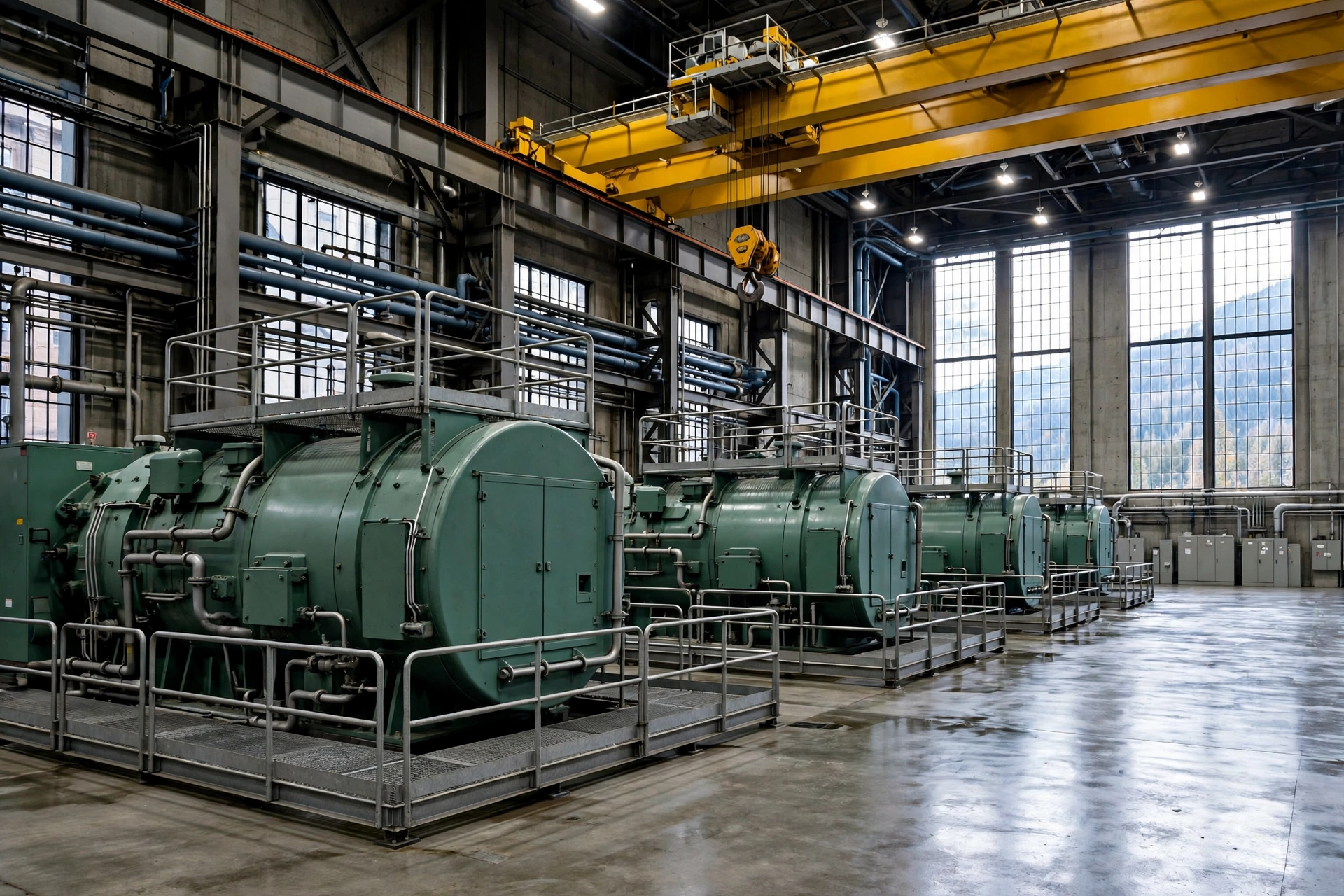
Sizing a diesel generator for a hydroelectric plant starts by listing the station service load, then applying three corrections: the starting transient of the largest motor, the load factor of the loads that run together, and the redundancy the plant needs. The generator sizing guide gives the general method; the numbers below apply it to three classes of hydroelectric plant. The bands are typical, not universal — the load list of the actual plant is the authority — but they give a buyer a figure to test a quotation against.
| Plant class | Installed capacity | Station service load | Diesel set |
|---|---|---|---|
| Small run-of-river | 5–25 MW | 30–80 kW | 100–150 kVA, single set |
| Medium cascade station | 50–300 MW | 250–400 kW | 2–3 × 500 kVA |
| Large multi-unit station | 500 MW and above | 500–1,000 kW and up | 1,000–2,000 kVA, N+1 |
A small run-of-river plant with two or three units of 5–10 MW each carries a station service load of 30–80 kW: gate hoists, governor oil pumps, cooling water, battery chargers, lighting and drainage. A single 100–150 kVA set covers it, with the battery carrying the DC loads through the 10-second start. The set is usually standby rated, because the plant’s annual outage hours are low and the set runs only for tests and real outages.
A medium station in the 50–300 MW range — the class that includes most of the cascade stations built in Laos, Nepal, Vietnam and East Africa — carries 250–400 kW of station service load. Two or three 500 kVA sets are the standard answer, and the reason is not only capacity. Three sets give N+1 redundancy: any one set can be out for service and the plant still has its full black-start capability. The sets also start in sequence, so the inrush of the largest motor is spread across machines that are already running.
A large multi-unit station above 500 MW carries 500–1,000 kW of station service load and more, and the answer is 1,000–2,000 kVA across two or more sets, often with a dedicated emergency set for the dam gates separate from the powerhouse sets. At this scale the set is almost always specified with a 400 V or 11 kV output and its own step-up transformer, and the switchgear is designed so that a single fault cannot take out both the normal station service supply and the emergency supply.
The Worked Example: Nam Ou 7, Laos
The clearest published example of a medium station’s auxiliary load is the Nam Ou 7 hydropower station on the Nam Ou River in northern Laos. The station is part of a seven-dam cascade totalling 1,272 MW, developed under a build-operate-transfer concession. Nam Ou 7 itself is 280 MW, with three 93 MW Francis turbine-generator units, connected to the national grid through a 230 kV switchyard. Its auxiliary power contract called for three 500 kVA diesel generator sets.
The load list published for the project is worth reading in full, because it is the whole sizing argument in one table:
| Auxiliary load | Running load |
|---|---|
| Governor oil pumps | 55 kW |
| Turbine bearing cooling water pumps | 75 kW |
| Generator hydrogen cooling | 30 kW |
| Excitation system | 20 kW |
| Intake gate hydraulic power unit | 90 kW |
| DC battery chargers | 15 kW |
| Control room | 25 kW |
| Total continuous | 310 kW |
Three 500 kVA sets give 1,500 kVA of installed capacity against a 310 kW continuous load. That looks like a four-to-one oversizing until the starting transients are added. The dewatering pump is 110 kW and starts direct-on-line at six times its running current. The intake gate unit draws 540 kW of inrush for half a second. The total inrush during the black-start sequence can reach 1,200 kW — 200% of a single set’s rating — for 0.3 to 0.5 seconds. The sets are sized for the transient, not the steady state, and the sequence is staged so that no single set ever sees the full transient alone.
The Lao power system security standard requires black start within 30 minutes of a system black event for all hydropower stations above 50 MW. The Nam Ou sets must start, synchronise and accept load entirely independent of any external power source — there is no grid reference voltage to synchronise against, so each set establishes the plant’s internal voltage from its own alternator. The site is eight hours from Luang Prabang by unpaved road in the wet season, and all equipment had to arrive in 20-foot ISO containers. The sets are rated for continuous 35°C ambient at 80% humidity, with 1,800 mm of annual rainfall concentrated between May and October.
The Honest Limit: What the Set Never Powers
The limit matters as much as the sizing. A diesel generator at a hydroelectric plant never powers the turbines’ output. A 280 MW station’s three 500 kVA sets total 1.5 MVA — about half of one percent of the station’s capacity. A 22,500 MW station’s 2 × 50 MW house units total 100 MW — less than half of one percent of its capacity. The set powers the loads that let the dam stay safe and the units restart. Any quotation that suggests a diesel set can carry a hydroelectric plant’s generation load is either misunderstanding the plant or overselling the set.
That limit is also what makes the set affordable. A 500 kVA silent set is a standard, factory-built machine. Three of them, with switchgear, fuel storage and a 30-minute black-start test regime, cost a small fraction of the station’s civil works. The Three Gorges house units are the exception that proves the rule: even the world’s largest dam keeps dedicated generation for its own loads, because the megawatt machines cannot be relied on to power themselves.
Black Start: The Hydro Plant’s Second Job
A hydroelectric plant has two jobs, and the second is the more valuable one. The first is to generate electricity. The second is to restart the grid after a blackout. Hydroelectric units are the fastest large machines to restart from a dead stop, they need almost no external power to do it, and they can absorb the reactive power of an unloaded transmission line while the grid is rebuilt. That combination is why system operators plan their restoration around hydroelectric plants, and why the diesel generator that enables a hydroelectric black start is grid infrastructure, not plant furniture.
Why Hydro Owns 40% of US Black Start
A 2019 report by Oak Ridge National Laboratory for the US Department of Energy found that hydropower provides about 40% of the United States’ black start resources, despite representing only about 10% of installed capacity. The reason is in the physics. A hydroelectric unit starts by opening the wicket gates with stored hydraulic pressure and flashing the field from the station battery. There is no boiler to warm, no gas turbine to crank, no fuel system to purge. A unit can go from standstill to synchronous speed in one to two minutes, and it can pick up load immediately.
A coal or gas plant, by contrast, needs its own auxiliary power for hours before it can generate: boiler feed pumps, draft fans, fuel handling, and a start that depends on the grid being available to supply them. That is the circular problem of grid restoration. The plants that could restart the grid cannot start without the grid. Hydroelectric plants break the circle, because their starting energy comes from water already sitting behind the dam and a battery already charged in the control room. The diesel generator’s job is to keep that battery charged and to power the oil pumps, cooling water and gate drives that the battery cannot carry on its own.
The 2003 Blackout: Hydro Led the Restoration
The northeast blackout of 14 August 2003 is the best-documented case. At about 4:10 pm, a cascade that began with a software failure in a FirstEnergy control room shut down more than 508 generating units at 265 power plants, cutting power to an estimated 50–55 million people across eight US states and Ontario. Most places were dark for hours; some areas waited up to four days.
Hydropower was the first generation back. The New York Power Authority’s Niagara and St. Lawrence-FDR projects operated continuously throughout the blackout, and within six hours of the start, NYPA’s hydroelectric generation was back online providing 3,794 MW — close to 45% of New York State’s total electricity load. The US–Canada task force report records that the surviving electrical island in western New York, anchored by Niagara and St. Lawrence hydroelectric generation, formed the basis for restoring service in New York and Ontario. The same pattern held in the great northeast blackout of 1965, when hydropower’s black-start capability was again the first resource used to rebuild the grid.
The lesson for a hydroelectric plant owner is direct. The grid operator’s restoration plan almost certainly names the plant as a black-start resource, and the plan assumes the plant can start without the grid. If the diesel set fails its monthly test, or the fuel tank is empty, or the battery is flat, the plan fails at its first step — and the operator will not discover that until the blackout is already happening. The automatic transfer switch that moves station service to the diesel set is therefore tested under load, every month, and the black-start sequence is rehearsed as a procedure, not assumed as a capability.
The Black-Start Sequence, Step by Step
A hydroelectric black start follows the same four stages as any other, but the hydroelectric version is shorter and simpler than most. First, the diesel set starts on its own batteries and establishes the station’s internal voltage — typically 400 V for the auxiliary bus. Second, the set energises the station service transformer and the essential bus, picking up the battery chargers, the control room and the governor oil pumps in a staged sequence. Third, the intake gate hydraulic unit opens the gates and the turbine is brought to speed-no-load, with the field flashed from the DC system. Fourth, the generator breaker closes, the step-up transformer and the first transmission line section are energised, and the unit begins picking up load and building the island that the rest of the grid will synchronise to.
The diesel set’s role ends when the first hydroelectric unit is carrying the station service load. At that point the set is unloaded, cooled down and returned to standby, and the plant runs on its own generation. The set has done its job in 20–30 minutes. Its fuel consumption over that period is trivial — a 500 kVA set at 75% load burns about 70 litres per hour — but the consequence of its failure is measured in hours of delayed restoration for millions of people. That is why the set is tested, fuelled and maintained to a standard that a standby set at a factory would never need.
Fuel, Placement and the Dam-Site Problem
A diesel generator at a hydroelectric plant lives in a harder place than a generator at a factory. The site is remote, the weather is extreme, the ground is wet, and the fuel has to arrive by a road that may itself be cut by the same storm that takes the grid down. The fuel and placement decisions are therefore part of the sizing, not an afterthought.
Fuel Autonomy: The 72-Hour Rule and the Real Numbers
A hydroelectric plant’s diesel set should be fuelled for 72 hours of continuous operation at the expected load, and the tank should be sized for the load the set will actually carry, not its nameplate rating. The arithmetic uses the set’s fuel consumption at the load factor it will run at, and the numbers are not small.
A Cummins C500D5 — 500 kVA standby / 455 kVA prime — burns 93.2 litres per hour at full prime load, 69.9 L/h at 75% load, 49.0 L/h at 50% load and 29.2 L/h at 25% load. Three such sets at 75% load burn about 210 litres per hour between them. Seventy-two hours at that rate needs 15,100 litres of fuel, and a seven-day autonomy needs 35,300 litres. At 50% load the same three sets burn 147 L/h, and 72 hours needs 10,600 litres.
Those figures decide the tank. A 15,000-litre bulk tank is a standard item, but it must be bunded, it must be above the flood line, and it must be filled before the wet season, not during it. Fuel that sits for a year between outages accumulates water from condensation, and diesel fuel ageing is the result: water breeds the microbes that block filters. The fuel should be tested and polished on a schedule, and the tank should be sized so that the fuel turns over — used in tests and topped up — rather than sitting for years. The maintenance schedule for the set should include a monthly loaded run of at least 30 minutes, a quarterly fuel sample, and an annual full-load test that proves the set can still carry the black-start sequence.
Placement: Above the Flood Line, Below the Noise Limit
Placement at a dam site has three constraints that a factory site does not. The first is flooding. The generator must sit above the maximum flood level, including the level that results from the dam’s own spillway operating at full discharge. A set placed in the powerhouse basement — a common mistake at older stations — is the first thing to flood when the drainage pumps lose power, which is precisely when the set is needed. The set belongs on a raised plinth, in a room or enclosure above the flood line, with its fuel tank bunded and its air intake above the water level.
The second constraint is access. The Nam Ou 7 site is eight hours from the nearest city by unpaved road in the wet season. A set that needs a specialist to start it, or a part that has to come from overseas, is a set that will not be available when it is needed. The sets at a remote dam should be standard, factory-built machines with parts available in the region, and the station staff should be trained to start, load and test them without outside help. The electrical substations article makes the same point for switchyard control power: the backup that matters is the one the local team can operate.
The third constraint is the environment. A dam site is humid, and a generator that sits idle in 80% humidity for months will grow condensation inside its alternator windings and its control panel. The set needs a space heater in the alternator, a dehumidified enclosure, and a monthly run that dries the windings out. It also needs protection from the dust of the construction and maintenance work that never stops at a dam, and from the vibration of the powerhouse itself. A set mounted on the powerhouse deck without isolation will transmit its vibration into the building and take the building’s vibration back.
Frequently Asked Questions
What size generator does a hydroelectric plant need?
A 5–25 MW run-of-river plant typically needs a 100–150 kVA set, a 50–300 MW station needs 500–1,500 kVA, and a 1,000 MW-plus plant needs 1,000–2,000 kVA across two or more sets. The figure comes from the station service load — gates, governors, excitation, cooling and control — plus the starting transient of the largest motor, not from the plant’s megawatt rating.
Do hydroelectric plants need a backup generator?
Yes. A hydroelectric plant loses its own power when the grid fails, because the units trip and the station service supply disappears with them. Without a diesel set, the plant cannot operate its spillway gates, cannot restart its units, and cannot perform the black start role the grid operator’s restoration plan depends on. The US Army Corps of Engineers requires two full-capacity, redundant station service sources at hydroelectric plants.
How long can a hydroelectric plant run on a generator?
A hydroelectric plant can run its essential loads on a diesel generator for as long as the fuel lasts — typically 72 hours on the installed tank, and a week or more with a bulk tank and a refuelling plan. The set does not power the turbines’ output, so the question is really about fuel autonomy: three 500 kVA sets at 75% load burn about 210 litres per hour, so 72 hours needs roughly 15,100 litres.
What happens to a hydroelectric plant during a power outage?
The units trip, the governor closes the wicket gates, and the turbines spin down. The station service supply is lost, and the plant goes dark except for the 125 V DC battery system, which carries protection and control for about 8 hours. If the diesel set starts, the plant can operate its gates, keep its bearings and governors alive, and restart a unit to begin grid restoration. If it does not, the plant waits for the grid to return — and the grid may be waiting for the plant.
Can a diesel generator power a hydroelectric plant?
A diesel generator can power a hydroelectric plant’s station service loads — gates, governors, excitation, cooling water, battery chargers and control — but it cannot power the plant’s generation output. A 280 MW station’s three 500 kVA sets total 1.5 MVA, about half of one percent of the station’s capacity. The set keeps the dam safe and the units restartable; the water makes the megawatts.
Specification Checklist
1. What is the station service load, load by load? Demand the load list: gate drives, governor oil pumps, bearing cooling water, excitation, battery chargers, control room, drainage and dewatering. Size the set from the list, not from a rule of thumb, and check the list against a published example such as Nam Ou 7’s 310 kW for a 280 MW station.
2. What is the largest single motor start? Ask for the locked-rotor kilovolt-amperes of the intake gate hydraulic unit and the dewatering pump, and for the total inrush of the black-start sequence. A set that cannot absorb a 540 kW gate inrush for half a second cannot open the intake gate.
3. Is the set rated for the duty and the site? Confirm the rating in standby and prime ratings terms, the ambient temperature and humidity rating, and the altitude derating if the dam is in the mountains. A set rated at 25°C and sea level is not the set that will run at a dam site at 35°C and 80% humidity.
4. Can the plant black-start in 30 minutes? Ask for the black-start procedure in writing, with the sequence, the loads at each step, and the test record. If the plant is above 50 MW on a grid that requires black start, the procedure is a regulatory obligation, not a preference.
5. Is the fuel enough for 72 hours, and is it fresh? Check the tank capacity against the set’s consumption at the expected load factor, and check the fuel test record. A 15,000-litre tank that has sat for two years without testing is not 15,000 litres of usable fuel.
6. Is the set above the flood line and reachable? Confirm the plinth height against the maximum flood level, the access road’s condition in the wet season, and that the station staff can start and load the set without outside help. A set that floods, or that nobody on site can operate, is not a backup.
7. Does the specification name the gates? The contract should state the gate loads, the black-start time, the fuel autonomy, and the test regime in full. If a supplier will not write those numbers down, the buyer has learned everything necessary about that supplier.
A hydroelectric plant is the only power station that can restart the grid, and the only one that can lose control of a reservoir while doing it. The diesel generator that stands behind it is a small machine with a large job: keep the gates moving, keep the bearings oiled, keep the battery charged, and put the first unit back on the bars. Size it from the load list, test it under load every month, and fuel it before the storm. For a station service load assessment and a quotation for a black-start-rated set, in open, silent or containerised configuration from 9 to 3750 kVA, contact PAVO.