

What Size Diesel Generator Does a Wind Farm Need? | PAVO
A wind farm that loses the grid does not stop generating because the wind stops. It stops because the turbines that make the power need power of their own — and nobody sized a generator for it.
What size generator does a wind farm need? A 50 MW onshore farm typically needs a 150–250 kVA set, a 300 MW farm needs 500–1,000 kVA, and a 1.2 GW offshore farm needs multiple sets totalling 1,000–2,000 kVA. The set powers yaw, pitch and control loads — never the turbines’ megawatt output.
- The Auxiliary Load Nobody Sizes For
- What Happens in the First 60 Seconds After Grid Loss
- The Storm Window: When Yaw Is the Difference Between Survival and Scrap
- Sizing the Set: From a Single Turbine to a 174-Turbine Farm
- Three Wind Farms, Three Answers
- Fuel Autonomy: How Long the Farm Lasts
- Frequently Asked Questions
- Specification Checklist
The Auxiliary Load Nobody Sizes For
A wind farm is the only power station that consumes electricity to produce electricity, and the consumption is not trivial. A turbine rated at 3 MW does not run on wind alone. It runs on wind plus a long list of electrical loads that keep the rotor pointed at the wind, the blades at the right angle, the gearbox oil warm and thin, the nacelle dry, and the controller awake. When the grid is up, those loads draw from the grid through the farm’s own collector network, and nobody notices. When the grid goes down, every one of those loads still needs power, and the only source left is whatever backup the farm has — usually a battery, sometimes nothing at all, and in a growing number of projects, a diesel generator.
The mistake is one of scale. A buyer who hears “50 MW wind farm” thinks in megawatts and sizes nothing, because the farm generates its own power. A buyer who hears “50 MW wind farm” and asks what it consumes discovers that the farm’s auxiliary load, parked and waiting for the grid to return, is 100–200 kW — a load the size of a small factory, running on nothing. The generator that covers it is not a token machine. It is a 150–250 kVA set, running for hours or days, in weather that stopped the grid in the first place.
The load list divides into three tiers, and the tiers decide the size, the rating and the fuel. The first tier is the turbine itself: yaw, pitch, heating and the gearbox. The second tier is the farm: the substation, the SCADA system, the protection relays and the communications link. The third tier is the site: the operations building, the yard lighting, the security system and the crew facilities. A generator sized for the third tier alone leaves the turbines blind. A generator sized for all three, with the motor starting surge included, is usually a third smaller than the set a buyer orders when they size by guesswork. The work is in the list, not in the nameplate.
Yaw: the motor that never stops working
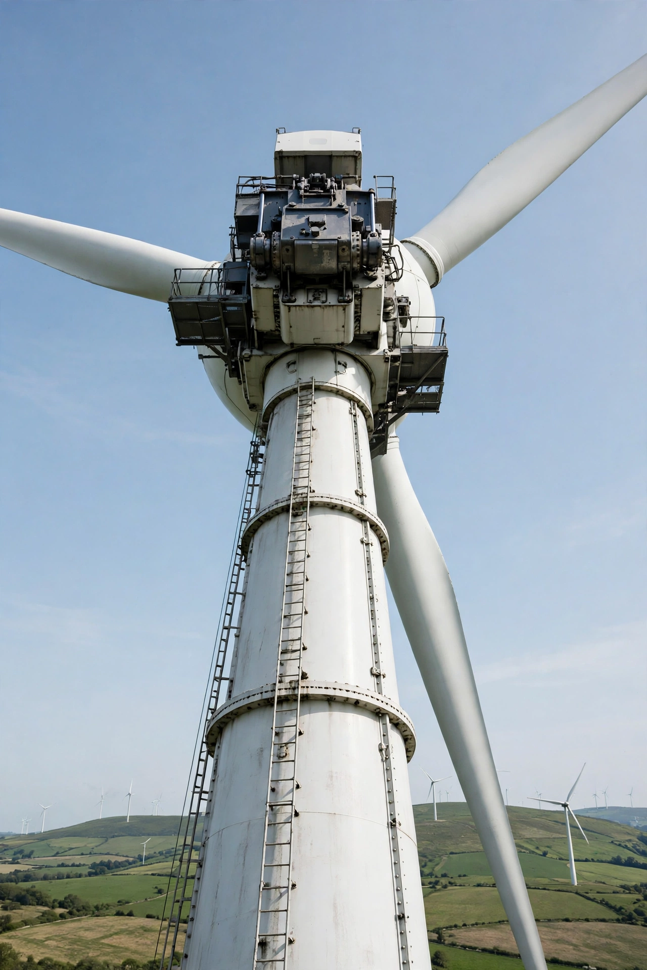
Yaw is the system that turns the nacelle so the rotor faces the wind. On a 3 MW onshore turbine, the nacelle and rotor together weigh 100–150 tonnes — on a GE 1.5 MW machine the nacelle and blades alone weigh 92 tonnes — and the yaw drives have to rotate that mass against the friction of the yaw bearing and the torque of the wind. The motors are small individually, 1.5–11 kW each, and a large turbine carries four to eight of them, but they do not run one at a time in steady state. When the wind shifts, several drives start together, and the starting transient is the problem: a yaw motor draws roughly five times its steady-state power for the first 5 seconds of a yaw move, a figure documented in recent wind-turbine power-consumption patents that size backup systems around exactly this transient. A single 5.5 kW yaw motor therefore demands 25–30 kVA for five seconds, and four of them starting in sequence demand 100 kVA of transient capacity from a generator that is otherwise carrying 20 kW.
The yaw drive also runs when the turbine is parked. A parked turbine in a storm is not a turbine at rest. It is a turbine that must keep facing into the wind, hour after hour, while the wind direction shifts around it. The yaw brakes hold the nacelle when the drives are idle, but every shift in wind direction is a yaw move, and every yaw move is a motor start. On a farm of 25 turbines in a storm, the yaw system is the most active load on the site, and it is the load the generator is least likely to have been sized for, because the load list was written on a calm day.
The motor starting calculation decides the generator size here, not the running load. A set sized on the running load alone — 20 kW of yaw, pitch and controls — trips the first time two turbines yaw together in a storm, because the transient demand is four to five times the running demand. The fix is the same as on any motor-heavy site: stagger the starts, size on the largest starting group, and check the voltage dip. A generator that dips more than 20% on a yaw start drops out the contactors on the pitch chargers and the SCADA power supplies, and the farm then hunts between starting and tripping while the storm does its work.
Pitch: the brake that runs on batteries
Pitch is the system that turns the blades, and it is the turbine’s primary brake. When the wind rises above the cut-out speed — about 25 m/s, or 55 mph, for most turbines according to the US Department of Energy — the controller pitches the blades edge-on to the wind, a position called feathering, and the rotor stops. When the grid fails, the pitch system has to do the same thing with no grid power at all. That is why every modern turbine carries its own emergency supply for pitch: batteries or ultracapacitors in the hub, one independent system per blade on machines like the ENERCON E-92, a 2,350 kW turbine with three independent pitch systems, each with its own emergency supply.
The emergency supply is sized for one job: feather the blades once. It is not sized to keep pitching them for hours. A typical pitch backup — KEBA’s PitchOne system, for example — carries a 10 F ultracapacitor bank at up to 550 V, with a projected life of 8–10 years and 500,000 cycles. That is enough energy to drive the blades to feather and hold them there. It is not enough to keep the turbine yawing, heating and communicating through a 48-hour outage. The distinction matters because buyers confuse the two: a turbine that can feather on its own batteries is a turbine that can stop safely, not a turbine that can survive a storm. Survival needs external power, and the external power is the generator.
The pitch motors themselves are 1.5–11.8 kW per blade on electric-pitch machines, and a 3 MW turbine carries three of them. In normal operation they draw 2–4 kW between them, mostly holding position. In an emergency feather they draw their full rated power for 30–60 seconds, and the backup charger that keeps the ultracapacitors or batteries topped up draws continuously. The load is small, but it is continuous, and it is the load that decides whether the turbine can be restarted when the grid returns. A pitch backup that has been drained by repeated feathering during a long outage, with no charger power to refill it, leaves the turbine unable to pitch at all — and a turbine that cannot pitch cannot be restarted, even when the grid comes back.
Heat, light and control: the load that never sleeps
The third group of turbine loads is the one buyers forget entirely, because it looks like housekeeping. The nacelle needs heating and dehumidifying: Vestas notes that power consumption for heating and dehumidification of the nacelle must be expected during periods of increased humidity, low temperatures and low wind speeds. The gearbox needs its oil heater, pump, cooler and filter system. The blades, in cold climates, need heating to prevent icing — and blade heating can consume 10–20% of the turbine’s rated power, which is 300–600 kW on a 3 MW machine. No backup generator is sized for blade heating; the correct answer is to switch it off during an outage and accept the icing risk, but the decision has to be made in advance, in the load-shedding plan, not discovered when the generator trips.
The control load is small and absolute: the turbine controller, the condition-monitoring system, the vibration sensors, the aviation obstruction lights and the data-collection electronics draw 1–2 kW per turbine, continuously, and they cannot tolerate a gap. A turbine whose controller is dark is a turbine nobody can see, command or diagnose. Multiply that by 25 turbines and the farm’s control load alone is 25–50 kW — a load that, on its own, justifies a 60 kVA set. Add the substation SCADA, the protection relays, the battery chargers and the communications link, and the farm’s standing load, parked and waiting, is 100–200 kW before a single yaw motor moves.
What Happens in the First 60 Seconds After Grid Loss
Grid loss at a wind farm is not like grid loss at a factory. A factory loses power and stops. A wind farm loses power and keeps moving: the wind does not stop because the grid did. The first 60 seconds decide whether the farm parks safely or takes damage, and the sequence runs on stored energy, not on the generator, because no diesel set starts and accepts load in under 10 seconds — and the farm needs power in under one second.
The automatic transfer switch is the first device in the chain. It detects the loss of grid voltage, starts the generator, and transfers the essential bus to it. The best automatic transfer switches complete the transfer in under 10 seconds; the generator itself needs 5–10 seconds to start, reach speed and accept load. That leaves a gap of up to 10 seconds in which the farm runs on nothing but the turbines’ own emergency supplies. The gap is short, but it is the most dangerous 10 seconds in the farm’s life, because the turbine that is spinning at full speed when the grid disappears has to be stopped, and the stopping is done by the pitch system on its own batteries.
Feathering on stored energy
The first thing that happens after grid loss is that the pitch system feathers the blades. On a turbine spinning at 15 rpm with the wind at 12 m/s, the pitch drives have seconds to move the blades from their working angle to feather. The energy comes from the hub batteries or ultracapacitors, which are sized for exactly this event, and the feathering succeeds — it succeeds every time the backup is healthy. The failures happen when the backup is not healthy: batteries that have aged past their 8–10 year design life, ultracapacitors that have lost capacitance in the cold, a charger that has been silently dead for months because nobody tested it under load. A pitch backup that fails leaves the rotor spinning with no grid to absorb its power, and the turbine overspeeds. The overspeed protection — the aerodynamic brake and the mechanical disc brake — then has to stop a rotor that the pitch system could not, and the loads on the blades and tower rise with the square of the wind speed.
The lesson is not that pitch backups are unreliable. It is that they are a single-use safety device with a finite life, and the generator is what keeps them charged. A farm whose generator never runs because the grid is reliable is a farm whose pitch backups are never tested under real conditions — and the first real test is the outage itself. The maintenance schedule for the generator and the pitch backup belong on the same page, with the same monthly test, because the two systems protect each other.
The yaw freeze
The second thing that happens after grid loss is that the yaw system stops. The yaw drives draw from the grid, and when the grid goes, they stop where they are. The nacelle is left pointing at wherever the wind was blowing when the grid failed, and the wind does not stay there. In a storm, the wind direction can shift 90 degrees in an hour. A turbine that cannot yaw is a turbine that is slowly turned side-on to the wind, and a side wind loads the blades and tower in ways the structure was not designed for. The yaw brakes hold the nacelle against the torque, but the brakes are designed to hold a nacelle that is facing the wind, not one that is being twisted sideways by a 25 m/s gust.
This is the failure that Typhoon Saomai exposed in 2006, and it is the reason modern turbines carry yaw power backup. The backup is a battery or ultracapacitor system dedicated to the yaw drives, sized to keep the nacelle facing the wind through a storm at wind speeds up to 70 m/s. It is a short-duration system: it buys hours, not days. When it is exhausted, the generator takes over — if the farm has one, and if the generator is wired to the yaw bus. Many farms do not wire it that way, because the yaw bus was never listed as an essential load when the electrical design was done. The generator powers the substation and the operations building, and the turbines sit in the dark, unable to turn, while the storm turns around them.
SCADA goes dark
The third thing that happens after grid loss is that the farm goes blind. The SCADA system, the fibre network, the meteorological mast, the condition-monitoring servers and the control-room screens all draw from the grid, and when the grid goes they go dark together. The operations team, sitting in a control room 50 km from the site, loses every turbine at once. They cannot see which turbines feathered, which pitch backups are low, which yaw drives are straining, or whether the substation battery is holding. They can see nothing until the generator starts and the communications link comes back — and if the generator is not wired to the SCADA bus, they see nothing until the grid returns.
The fix is a load list that treats the SCADA system as a protection load, not as an office load. The SCADA servers, the fibre multiplexers, the microwave radios and the met mast draw 5–15 kW for a 50 MW farm, and they belong on the essential bus, on the generator, with the same priority as the yaw drives. The remote monitoring system that watches the farm from another country is worthless if its power supply is the grid that just failed, and the farm that cannot be seen cannot be protected.
The Storm Window: When Yaw Is the Difference Between Survival and Scrap
Every turbine is designed to survive a storm. The design standard, IEC 61400-1, sets the survival wind speed, the loads the tower and foundation must carry, and the control system that parks the turbine before those loads are exceeded. The standard assumes one thing that a grid failure removes: that the turbine can keep facing the wind. A turbine that faces the wind in a 50 m/s storm carries a fraction of the load of a turbine that is turned 30 degrees sideways in the same storm, because the parked, feathered blades present their narrow edge to the wind. Turn the nacelle sideways and the broad face of the blades catches the wind, the thrust on the tower multiplies, and the loads leave the design envelope. The storm does not have to exceed the design wind speed to destroy the turbine. It only has to outlast the yaw backup.
The window is measured in hours. A yaw power backup system carries the yaw drives for 2–6 hours, depending on the turbine and the storm. A diesel generator carries them for as long as its fuel lasts. The difference between those two numbers is the difference between a turbine that survives a storm and a turbine that is written off, and the difference is decided at the design stage, when the generator is either specified as part of the farm’s storm-survival system or left out because “the turbines have their own batteries.”
Typhoon Saomai, 2006
The case that changed the industry happened in August 2006, when Typhoon Saomai struck the coast of Zhejiang province in China. Saomai was a super typhoon, with gusts above 60 m/s, and it hit a wind farm on the coast. The grid failed early in the storm, as grids do in typhoons, and the turbines lost their yaw power. The pitch systems feathered the blades on their own batteries, and the turbines parked — but they could not yaw. As the typhoon’s wind direction rotated around the site, the parked turbines were left facing the wrong way, and the side loads on the blades and towers exceeded the design limits. Turbines were damaged. The lesson, recorded in the industry’s post-storm analysis, was that grid loss can kill yaw control, and that a turbine that cannot yaw in a storm is a turbine at risk even when its blades are feathered.
The industry’s answer was yaw power backup: a dedicated battery or ultracapacitor system that keeps the yaw drives alive when the grid fails, sized to hold the nacelle into the wind at speeds up to 70 m/s. The answer works for the storm it was designed for. It does not work for the storm that lasts longer than the battery, or for the farm where the yaw backup was never maintained, or for the turbine whose yaw backup was sized for a 2-hour outage and the grid stayed down for 18 hours. The diesel generator is the second layer: it takes over when the battery is exhausted, and it keeps the yaw drives turning for as long as the fuel lasts. A farm that has both layers — battery for the first hours, diesel for the rest — survives storms that destroy farms with one layer or none.
Yaw power backup and the diesel supplement
The modern yaw power backup system is a small, dedicated piece of equipment. It sits in the nacelle or the tower base, it charges from the grid in normal operation, and it discharges into the yaw drives when the grid fails. The newest designs can be supplemented with an external diesel generator, allowing the yaw system to operate independently even if the grid fails during a power shortage — a design that is now written into turbine manufacturers’ own patent filings. The generator does not replace the battery. It replaces the grid as the battery’s charger, and it powers the yaw drives directly once the battery is flat.
The practical consequence for sizing is that the generator must be able to carry the yaw load of the whole farm, not just the substation. The yaw load of a 25-turbine farm, with each turbine carrying four 5.5 kW yaw motors and one yawing at a time, is 5.5 kW of running load per turbine and 25–30 kVA of starting transient — but the farm does not yaw one turbine at a time in a storm. It yaws them in sequence, as the wind direction shifts, and the generator sees a series of 25–30 kVA transients, one after another, for hours. A generator sized on the running load alone trips on the second or third transient. A generator sized on the largest starting group, with staggered yaw starts written into the farm’s control logic, carries the storm without tripping. The staggering has to be programmed: the farm controller must be told to yaw no more than two turbines at once when running on backup power, and the generator must be sized for those two. That is a line of code and a line in the specification, and it is the difference between a farm that survives and a farm that trips its own generator in the first hour of the storm.
Sizing the Set: From a Single Turbine to a 174-Turbine Farm
Sizing a wind farm generator starts with a load list, not with a rule of thumb. The generator sizing guide method applies here exactly as it does anywhere else: list every essential load, separate the continuous loads from the motor loads, add the starting surge of the largest motor group, and check the result against the generator’s transient voltage dip. The difference at a wind farm is that the continuous load is dominated by the control systems and the substation, and the motor load is dominated by the yaw drives. The tables below give the typical bands. They are starting points for a load study, not a substitute for one.
The per-turbine load list
A 3 MW onshore turbine, parked and waiting for the grid, carries the following essential loads. The figures are typical for a modern geared turbine with electric pitch; direct-drive machines carry less gearbox load and more converter load, and the load list should be taken from the turbine manufacturer’s own auxiliary-power data, not from this table alone.
| Load | Running kW | Starting kVA |
|---|---|---|
| Yaw drives (4 x 5.5 kW, one yawing at a time) | 5.5 | 25–30 |
| Pitch system (3 blades, servo + backup charging) | 2–4 | 8–12 |
| Nacelle heating and dehumidifying | 3–8 | 3–8 |
| Gearbox oil heater, pump and cooler | 2–5 | 8–15 |
| Controls, SCADA, aviation lights | 1–2 | 1–2 |
| Blade heating (cold climate, normally shed) | 30–60 | 30–60 |
| Total, blade heating shed | 14–24 | 45–70 |
The total is the number that surprises buyers: a parked 3 MW turbine draws 14–24 kW of essential load, and demands 45–70 kVA of starting capacity when its yaw drive and pitch system move together. Multiply by 25 turbines and the farm’s parked load is 350–600 kW running, with a starting transient that can reach 1,000 kVA if the yaw moves are not staggered. No farm sizes its generator for all turbines yawing at once, because they never do — but the generator must be sized for the largest group the control system allows to yaw together, and that number has to be written down, in the specification, before the generator is ordered.
Sizing bands by farm size
The bands below assume the blade heating is shed during an outage, the yaw starts are staggered to no more than two turbines at a time, and the substation and SCADA loads are included. They are for the essential load only: the load that keeps the farm safe, controllable and restartable. A farm that also wants to keep its operations building heated, its workshop powered and its crew fed needs a larger set, and that is a separate decision.
| Farm size | Turbines | Parked essential load | Typical generator set | Fuel at 75% load |
|---|---|---|---|---|
| 10–20 MW onshore | 5–10 | 70–150 kW | 100–200 kVA | 16–32 L/h |
| 50 MW onshore | 20–25 | 150–300 kW | 150–250 kVA | 25–40 L/h |
| 100 MW onshore | 30–50 | 300–600 kW | 300–500 kVA | 50–80 L/h |
| 300 MW onshore | 100–150 | 600–1,200 kW | 500–1,000 kVA | 80–160 L/h |
| 1.2 GW offshore | 174 | 1,200–2,000 kW | 1,000–2,000 kVA, multiple sets | 160–320 L/h |
The spread inside each band is wide because farms vary more than factories do. A 50 MW farm of 25 × 2 MW turbines with small nacelles and no blade heating sits at the bottom of its band. The same 50 MW built from 17 × 3 MW turbines with heated blades, a large substation and a staffed operations building sits at the top. The only way to know where a given farm sits is to build the load list from the turbine datasheets and the substation single-line diagram. A set bought on the megawatt rating alone is a guess, and the guess is usually too large, which costs money, or too small, which costs the farm.
The rating to use is standby, ESP, and the set should be loaded to at least 30% on its monthly test run. The standby and prime ratings guide explains why a standby set run at light load for years is a set that will not start when the grid fails — and a wind farm generator is the worst case for light-load running, because its real load is 15–25% of its rating most of the time, and it only sees its full load in the storm that needs it most. The monthly test has to be a load test, with a load bank, not a no-load run. A generator that has only ever run at 20% load will wet-stack, glaze its bores and fail its first real storm.
Three Wind Farms, Three Answers
The same sizing method gives three very different answers on three real kinds of farm, because the load list, the fuel logistics and the consequence of failure are different in each case. The cases below are composites built from published farm data and from the load figures in the tables above. They are not quotations. They are the arithmetic a buyer should do before the order is placed.
Case 1: A 50 MW onshore farm in Inner Mongolia
A 50 MW onshore farm in Inner Mongolia carries 25 × 2 MW turbines across a steppe site where winter temperatures fall to -30°C and the grid is a single 110 kV line across open country. The turbines carry blade heating, because icing is a winter certainty, and the blade heating alone draws 200–400 kW per turbine when it is on — more than the entire parked essential load of the farm. The load-shedding plan is therefore the first document in the specification: blade heating is shed on grid loss, the nacelle heaters stay on, and the generator carries yaw, pitch, controls and the substation.
The parked essential load is 150–200 kW, and the starting transient of the largest yaw group is 60–90 kVA. The answer is a 200 kVA silent set with a Cummins or Weichai engine, burning about 32 L/h at 75% load, with a 2,000 L bulk tank. That combination gives 62 hours of running before refuelling — two and a half days, which is the time a fuel tanker needs to reach a steppe site in winter. The set sits in the substation compound, inside a heated enclosure, because a generator that will not start at -30°C is a generator that does not exist. The block heater runs from the grid in normal operation and from the set’s own battery charger during an outage, and the fuel is winter-grade diesel, because summer diesel waxes at -15°C and the farm would then have a generator full of fuel it cannot burn. The diesel fuel ageing guide covers the storage and testing regime that keeps that fuel usable through a winter it was bought in the autumn for.
The failure this set prevents is the quiet one: a winter storm that takes the 110 kV line down for 36 hours, the turbines parked, the yaw backups exhausted after 4 hours, and the nacelles slowly turning side-on to a 25 m/s wind while nobody can see them because the SCADA is dark. With the generator, the yaw drives keep working, the SCADA stays up, and the farm restarts the morning the line is repaired. Without it, the farm restarts with a damage survey.
Case 2: A 1.2 GW offshore farm in the North Sea
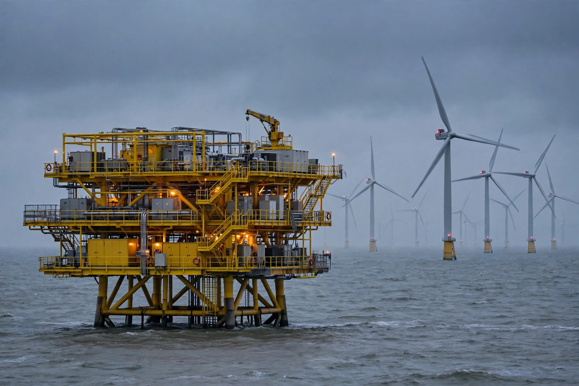
Hornsea One, off the Yorkshire coast, is 1,218 MW across 174 Siemens Gamesa SWT-7.0-154 turbines, covering 407 square kilometres and powering more than a million UK homes. It is the largest offshore wind farm in the world, and its backup power problem is the opposite of the Inner Mongolia farm’s: the load is enormous, the site is 120 km from shore, and the fuel arrives by boat. The turbines are 7 MW machines, and the parked essential load of the whole farm is 1,200–2,000 kW — a load the size of a small town’s substation, running on nothing when the export cable trips.
The answer is not one generator. It is several, in the right places. The offshore substation platform carries its own diesel set, typically 500–1,000 kVA, powering the platform’s control systems, the protection relays, the battery chargers, the communications link and the helideck and crane loads. The turbines themselves carry their yaw power backup and pitch backup, and the farm’s emergency plan accepts that the turbines will park and wait: the generator’s job is to keep the platform alive and the export cable ready to re-energise, not to keep 174 turbines yawing. The fuel is stored on the platform in a bunded tank, typically 10,000–20,000 L, giving 60–120 hours at 160 L/h — and the resupply is a crew transfer vessel or a supply boat, weather permitting. In a North Sea winter, weather does not always permit, and the fuel autonomy has to cover the worst gap, not the average one.
The failure this arrangement prevents is the one that costs the most: an export-cable fault that takes the farm off the grid for a week, the platform dark, the batteries flat, and the 174 turbines parked with no way to know whether their pitch backups are healthy. With the platform generator, the control room keeps its view of the farm, the protection relays stay armed, and the re-energisation is a controlled sequence, not a gamble. The cost of the generator and its fuel is a rounding error against the revenue of a 1.2 GW farm: at a wholesale price of £50/MWh, a single day at full output is £1.46 million, and at a typical offshore capacity factor of 45% it is still about £650,000. The generator pays for itself the first time it is needed, and it is needed the first time the cable trips in winter.
Case 3: A remote hilltop site with 12 turbines
The third case is the one most often built and least often protected: a 12-turbine hilltop site, 24 MW, at the end of a single-track road in the highlands, where the grid connection is a 33 kV spur and the nearest fuel station is 40 km away. The turbines are 2 MW machines, the parked essential load is 70–100 kW, and the answer is a 125 kVA set in a weatherproof canopy at the substation, burning about 20 L/h at 75% load, with a 1,000 L bunded tank. That gives 50 hours — two days — before a fuel delivery is needed, and the delivery is a 4×4 tanker on a road that closes in snow.
The failure this set prevents is the mundane one: a winter outage that lasts 30 hours, the yaw backups exhausted after 4 hours, and the turbines left side-on to the wind while the road is closed and nobody can reach the site. The generator keeps the yaw drives turning, the SCADA link up, and the site visible from the control room 80 km away. The remote monitoring system is the farm’s only eyes during the outage, and it runs on the generator. Without the set, the site is blind, the turbines are unprotected, and the first person to know about the damage is the maintenance crew that drives up when the road reopens.
The lesson across all three cases is the same: the generator is sized to the auxiliary load, not to the megawatts, and the fuel is sized to the access, not to the tank. A farm that a tanker can reach in 4 hours needs 24 hours of fuel. A farm that a boat can reach in 3 days, weather permitting, needs 7 days of fuel. The megawatts decide the revenue. The access decides the tank.
Fuel Autonomy: How Long the Farm Lasts
A wind farm generator is a standby machine that runs in the worst weather, at the end of the worst road, for the longest outage the site has ever seen. Its fuel autonomy is not a number on a datasheet. It is a contract with the fuel supplier, the road, the sea and the season. The arithmetic is simple: fuel burn at 75% load, multiplied by the hours the site must survive without a delivery, plus a margin for the delivery that is late. The judgement is in the hours, and the hours are set by the access.
Fuel burn and tank sizing
The table below gives the fuel burn for the common set sizes at 75% load, and the autonomy on the tank sizes farms actually install. The burn figures are for a modern turbocharged diesel at 75% load; at 50% load the burn falls by roughly a third, and at 100% load it rises by roughly a quarter. The autonomy figures assume the set runs continuously at 75% load, which is the conservative assumption: in practice the load varies, and the set runs lighter at night and heavier in a storm.
| Generator set | Fuel at 75% load | Autonomy on 1,000 L | Autonomy on 5,000 L | Autonomy on 10,000 L |
|---|---|---|---|---|
| 125 kVA | 20 L/h | 50 hours | 250 hours | 500 hours |
| 250 kVA | 40 L/h | 25 hours | 125 hours | 250 hours |
| 500 kVA | 65 L/h | 15 hours | 77 hours | 154 hours |
| 1,000 kVA | 130 L/h | 8 hours | 38 hours | 77 hours |
The right tank is the one that covers the longest outage the site has seen, plus the longest delivery delay, plus 24 hours. A 50 MW onshore farm with a 250 kVA set and a 5,000 L tank has 125 hours — five days — which covers a 72-hour outage and a 48-hour delivery delay with a day to spare. A 1.2 GW offshore farm with a 1,000 kVA set and a 10,000 L tank has 77 hours — three days — which is tight for a North Sea winter, and the correct answer is usually a larger tank or a second tank, not a smaller generator. The tank is cheap. The outage is expensive.
The fuel itself needs the same attention as the tank. Diesel left in a tank for a year absorbs water, grows microbes and loses its cetane, and a wind farm generator is the classic victim: it runs for 20 hours a year on test, and the fuel in its tank is two years old when the storm arrives. The fuel should be tested annually, polished or replaced on a schedule, and the tank should be kept full, because a full tank condenses less water than a half-empty one. The diesel fuel ageing article covers the testing regime in detail; the point here is that a generator with bad fuel is a generator that does not start, and a wind farm generator that does not start is a farm with no backup at all.
The offshore fuel problem
Offshore, the fuel problem is not the tank. It is the boat. A crew transfer vessel carries 1,000–2,000 L of diesel if it carries any at all, and a supply boat carries more but sails less often and only in weather a crew transfer vessel would refuse. The fuel delivery to an offshore substation is therefore a planned operation, not a phone call: it is scheduled, it is weather-dependent, and it is cancelled more often than it is completed in winter. The autonomy calculation for an offshore farm has to assume that the next delivery is 7 days away, not 24 hours, and the tank has to be sized for that.
The second offshore problem is the fuel’s own storage. A bunded tank on an offshore platform sits in salt air, in a space where every kilogram of weight was argued over in the design, and where a leak is a marine pollution incident, not a puddle. The tank is double-skinned, bunded to 110% of its volume, and fitted with a level gauge that reports to the SCADA system, because a tank that is found empty during an outage is a tank that was never checked. The fuel transfer pump is on the essential bus, so it runs on the generator, and the day tank on the platform is filled automatically, because nobody is on the platform at 3 a.m. in a storm to fill it by hand. The offshore generator is a system, not a machine, and the system includes the tank, the pump, the gauge, the boat and the weather window.
Frequently Asked Questions
What size generator does a wind farm need?
A 50 MW onshore farm typically needs a 150–250 kVA set, a 300 MW farm needs 500–1,000 kVA, and a 1.2 GW offshore farm needs multiple sets totalling 1,000–2,000 kVA. The set is sized to the parked auxiliary load — yaw, pitch, controls and the substation — never to the farm’s megawatt output. A load list from the turbine datasheets and the substation single-line diagram is the only reliable basis for the size.
Do wind farms need a backup generator?
Yes, where the farm must survive a grid outage in a storm. The turbines’ own pitch and yaw backups last hours; a diesel generator lasts as long as its fuel does. Farms in typhoon and hurricane regions, offshore farms, and remote onshore sites with long grid-restoration times are the cases where a generator is essential. A farm on a strong urban grid with short outages can often rely on the turbines’ own backups alone.
How long can a wind farm run on a generator?
As long as its fuel lasts. A 250 kVA set on a 5,000 L tank runs about 125 hours at 75% load; a 1,000 kVA set on a 10,000 L tank runs about 77 hours. The practical limit is fuel delivery, not the generator: an onshore farm a tanker can reach in a day can run indefinitely, while an offshore platform that depends on a supply boat is limited by the weather window and the tank size.
What happens to a wind farm during a power outage?
The turbines pitch their blades to feather on their own battery or ultracapacitor backup and park, the yaw drives stop where they are, and the SCADA system goes dark. If the outage lasts longer than the pitch and yaw backups — typically a few hours — the turbines can no longer face the wind, and in a storm the side loads on the blades and tower can exceed the design limits. A backup generator keeps the yaw drives turning, the pitch backups charged and the SCADA link alive.
Can a diesel generator power a wind turbine?
A diesel generator cannot power a wind turbine’s megawatt output — and it is never asked to. It powers the turbine’s auxiliary loads: the yaw motors at 1.5–11 kW each, the pitch system, the nacelle heating, the gearbox oil system and the controls, typically 14–24 kW per parked 3 MW turbine. The generator keeps the turbine safe, controllable and restartable during a grid outage; the wind, when it returns, does the generating.
Specification Checklist
- Build the load list from the turbine datasheets. List every essential load per turbine — yaw, pitch, nacelle heating, gearbox oil system, controls and aviation lights — and the substation loads: SCADA, protection relays, battery chargers and communications. Size the generator on the largest starting group, not on the running load.
- Write the yaw staggering into the control logic. Limit simultaneous yaw moves to two turbines when running on backup power, and size the generator for those two. A generator that trips on the second yaw transient is a generator that was sized on a calm day.
- Put the SCADA bus on the essential bus. The SCADA servers, the fibre multiplexers, the microwave radios and the met mast belong on the generator, with the same priority as the yaw drives. A farm that cannot be seen cannot be protected.
- Shed the blade heating on grid loss. Blade heating can draw 10–20% of a turbine’s rated power. Write the load-shedding plan before the outage, not during it, and make sure the generator never sees that load.
- Size the fuel to the access, not to the tank. A farm a tanker can reach in 4 hours needs 24 hours of fuel. A farm a boat can reach in 3 days, weather permitting, needs 7 days of fuel. Test the fuel annually and keep the tank full.
- Test the generator under load, every month. A load-bank test at 30% load or more, with the yaw and pitch loads connected, is the only test that proves the set will carry the farm. A no-load run proves only that it starts.
- Check the rating letters on the datasheet. The set should be standby-rated, ESP, for a farm that runs it a few hundred hours a year. The standby and prime ratings article explains the difference, and why a standby set run at 20% load for years will not start when the storm arrives.
A wind farm is a power station that needs power of its own, and the generator that supplies it is sized in kilowatts, not megawatts. Get the load list right, stagger the yaw starts, keep the fuel fresh and the tank full, and the farm will be standing when the grid comes back. To size a set for a specific farm — onshore or offshore, 10 MW or 1.2 GW — contact PAVO with the turbine model, the turbine count, the substation voltage and the site access, and PAVO will price the correct set from those four lines.