

What Size Generator Does a Substation Need? | PAVO
A substation is the one place on the grid where a power cut does not just switch the lights off. It switches off the equipment that is supposed to switch the grid back on.
What size generator does a substation need? A 33/11 kV distribution substation typically needs a 30–100 kVA set, a 132 kV transmission station needs 100–250 kVA, and a 220/400 kV station needs 250–500 kVA. The generator powers control and station service only — never the grid load.
- What a Substation Actually Runs On
- Sizing the Set: Three Substation Classes, Three Answers
- The Battery Clock: Eight Hours, Then Darkness
- Three Substations, Three Outages
- Fuel Autonomy: How Long the Station Lasts
- Where the Generator Sits: EMF, Oil and the Fence Line
- Frequently Asked Questions
- Specification Checklist
What a Substation Actually Runs On
A substation’s own electrical load is small, and that is exactly why buyers get it wrong. A 132 kV substation may pass 100 MVA through its transformers on a normal day, and its own station service — everything the site needs to run itself — may draw 60–150 kW. The ratio is roughly a thousand to one. The generator that backs up a substation is therefore a small machine by grid standards, typically 30–500 kVA, and its job is not to keep the power flowing to customers. Its job is to keep the substation itself alive, controllable and able to be switched back on when the grid returns. A substation that loses its own power cannot trip a breaker, cannot close a breaker, cannot tell the control centre what happened, and cannot take part in restoring the network. It becomes a passive piece of steel in a fence, waiting for a crew to drive to it.
The load list divides into three tiers, and the tiers decide the size, the rating and the fuel. The first tier is protection and control: the loads that must never blink. The second tier is station service: the loads that keep the yard working. The third tier is auxiliary: the loads that keep people safe and the site secure. A generator sized for the third tier alone leaves the protection system dead. A generator sized for all three tiers, with the motor starting surge included, is usually a third smaller than the set a buyer orders when they size by guesswork. The work is in the list, not in the nameplate.
Protection and control: the load that cannot blink
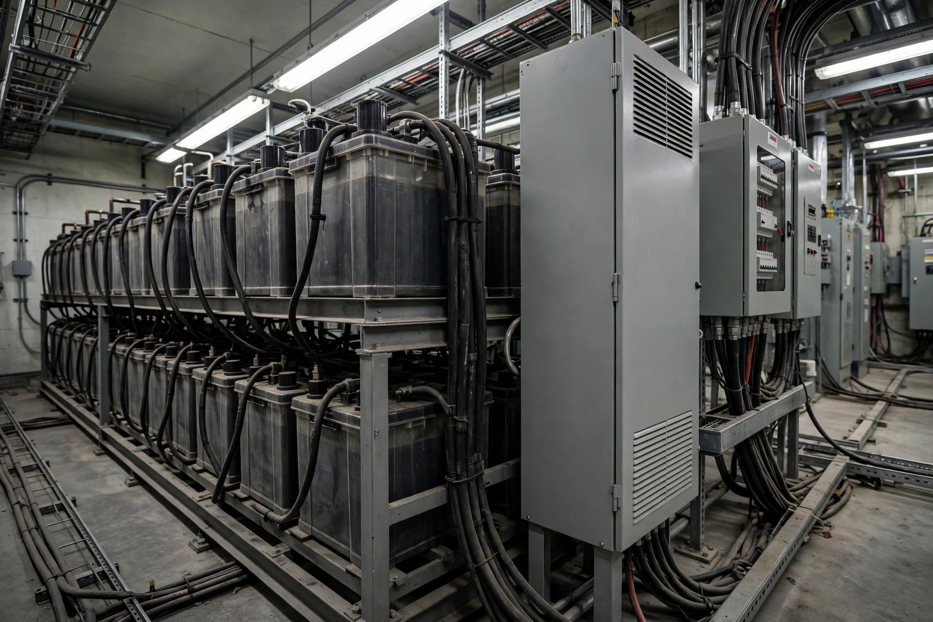
Protection and control is the reason the substation has a battery, and the battery is the reason the substation has a generator. The protection relays, the intelligent electronic devices, the SCADA remote terminal unit, the communications equipment and the GPS time source all run on the station DC system, almost always 125 V DC for trip and close circuits and 48 V DC for communications. The DC system exists because AC cannot be trusted during a fault: a short circuit on the network drags the AC voltage down at exactly the moment the protection relay needs power to clear it. The battery breaks that dependency. It carries the relays, the trip coils and the interlocking logic through any AC disturbance, for as long as its charge lasts.
The trip coil is the smallest load with the largest consequence. A circuit breaker trip coil draws a few amps for 50–100 milliseconds — almost nothing in energy terms — but without it the breaker cannot open, and a breaker that cannot open cannot clear a fault. The close coil is the same. The motor operator on a disconnect switch draws more, 2–5 kW for the few seconds it takes to move the blades, and a station with motor-operated disconnects on every bay can see several of those motors start in sequence during a switching operation. The protection relays themselves draw little, 10–30 W each, but a transmission substation carries dozens of them, plus merging units, plus the station bus, plus the engineering workstation. The communications load — fibre multiplexers, microwave radios, power-line carrier — draws 1–5 kW continuously and cannot tolerate a gap, because the control centre’s view of the station dies with it.
North American reliability rules treat this DC system as protection equipment, not as a building service. NERC standard PRC-005 includes the station DC power supply associated with a protective function — the batteries, the battery chargers and the DC distribution — in the maintenance and testing obligations that apply to protection systems. A battery that is not maintained on schedule is a protection-system violation, not a housekeeping failure. That is the regulatory weight behind a load that draws less power than a domestic kettle.
Station service: the load that keeps the yard working
Station service is the AC load of the site, and it is dominated by the battery chargers. A transmission substation typically carries two 125 V battery chargers, each rated 20–50 A, running in parallel with one in service and one on standby. After a discharge, the charger in service has to carry the continuous DC load and recharge the battery at the same time, which is why charger sizing is set by the recharge requirement, not by the steady load. A charger that is too small leaves the battery only partly recharged after an outage, and the next outage starts with a battery that is already short. The generator that feeds the charger has to carry that recharge load for 8–24 hours, which is the time IEEE 946 recommends for restoring a battery to about 95% of capacity.
The second station-service load is transformer cooling. A power transformer with ONAN cooling needs no fans, but a transformer with ONAF or OFAF cooling — forced air, forced oil — depends on its cooling fans and oil pumps to carry its rated load. A 40 MVA transformer at 132 kV may carry 6–12 kW of cooling fans, and a 240 MVA autotransformer at 400 kV may carry 30–60 kW. The fans start as motors, and motors start hard: a fan motor started direct-on-line draws 6–7 times its running current for the first second. The generator’s starting-kVA calculation has to include the largest fan group starting together, or the set trips on the first hot day the grid fails. The tap changer motor, the cooling pump motors and the motor-operated disconnects belong in the same calculation.
The third station-service load is the control building itself. A transmission substation control building carries heating, ventilation and air conditioning for the relay panels, the battery room and the communications room, and the HVAC load is often the largest single AC load in the building: 10–40 kW depending on climate and building size. The battery room needs ventilation to clear hydrogen, the relay room needs a stable temperature for the electronics, and the communications room needs cooling for equipment that runs continuously. A generator that cannot carry the HVAC leaves the relays cooking in their own heat on a summer outage, and a battery room without ventilation accumulates hydrogen from a charging battery. The yard lighting, the sump pumps and the water supply sit below the HVAC in size but above it in consequence: a dark yard at 2 a.m. is a yard nobody can work in safely.
Auxiliary loads: the load that keeps people safe
The auxiliary tier is the smallest in kilowatts and the hardest to argue against in a safety review. Emergency lighting in the control building and along the yard access routes draws 2–5 kW and must come up the instant the grid fails, because a substation in the dark is a site full of high-voltage equipment that nobody can see. The fire alarm panel, the fire suppression system and the security system — CCTV, access control, intrusion detection — draw 1–3 kW between them and run continuously. A substation that loses its security system during a blackout is an unmanned, unfenced, high-value site with no eyes on it, and copper theft from substations during outages is a documented problem in several markets.
The workshop and the test equipment draw little and are often left off the essential bus, which is the right call. A substation generator is not there to power a welder or a compressor. It is there to power the loads that keep the station safe, controllable and restorable. Every kilowatt spent on a non-essential load is a kilowatt taken from the battery charger, and the battery charger is the load that decides whether the station is ready for the next outage.
Sizing the Set: Three Substation Classes, Three Answers
Substation sizing starts with a load list, not with a rule of thumb. The generator sizing guide method applies here exactly as it does anywhere else: list every essential load, separate the continuous loads from the motor loads, add the starting surge of the largest motor group, and check the result against the generator’s transient voltage dip. The difference at a substation is that the continuous load is dominated by the battery chargers and the HVAC, and the motor load is dominated by cooling fans and motor-operated disconnects. The table below gives the typical bands. They are starting points for a load study, not a substitute for one.
| Substation class | Typical station-service load | Typical generator set | Fuel at 75% load | Autonomy on 1,000 L |
|---|---|---|---|---|
| 33/11 kV distribution | 15–40 kW | 30–100 kVA | 8–16 L/h | 60–125 hours |
| 132 kV transmission | 60–150 kW | 100–250 kVA | 20–40 L/h | 25–50 hours |
| 220/400 kV transmission | 150–350 kW | 250–500 kVA | 45–80 L/h | 12–22 hours |
The spread inside each band is wide because substations vary more than factories do. A 33/11 kV substation with two 10 MVA transformers, a 50 kVA station service transformer and a small control building sits at the bottom of its band. The same voltage class with four transformers, outdoor switchgear, a large battery and a staffed control building sits at the top. The only way to know where a given station sits is to measure or calculate the load list. A set bought on the voltage class alone is a guess, and the guess is usually too large, which costs money, or too small, which costs the station.
A 33/11 kV distribution substation: 30–100 kVA
A distribution substation is the most common substation on any network, and the easiest to oversize. A typical site carries two 10 MVA transformers stepping 33 kV down to 11 kV, feeding a dozen outgoing feeders through indoor or outdoor switchgear. The station service transformer is usually 50 kVA, and the essential load list reads: two 125 V battery chargers at 20 A each, protection relays and SCADA at 3–5 kW, control building HVAC at 8–15 kW, yard lighting at 2–3 kW, sump pumps at 2–4 kW, and security and communications at 1–2 kW. The total continuous load lands at 20–35 kW, and the largest motor start is a cooling fan group or a sump pump at 5–10 kVA of starting demand.
A 60 kVA set covers that list with room to spare. A PAVO 60 kVA silent set with a Cummins or Weichai engine burns roughly 10 L/h at 75% load, which is about 45 kW, and carries a 200 L sub-base tank as standard. That combination gives 20 hours of running before refuelling, and a 1,000 L bulk tank extends it past four days. The mistake at this voltage class is buying a 150 kVA set for a 30 kW load: the engine then runs at 20% load, wets stacks, glazes its bores and fails its next load test. The rating to use is standby, ESP, and the set should be loaded to at least 30% on its monthly test run. The standby and prime ratings guide explains why a standby set run at light load for years is a set that will not start when the grid fails.
A 132 kV transmission substation: 100–250 kVA
A 132 kV substation is where the load list starts to bite. The site typically carries two or three 40–90 MVA transformers, air-insulated or gas-insulated switchgear across several bays, and a control building with two battery systems, sometimes 125 V for protection and 48 V for communications. The battery chargers grow to 30–50 A each, the cooling fans on the transformers add 10–25 kW, the motor-operated disconnects add a starting surge of 15–30 kVA when a bay is switched, and the control building HVAC grows to 15–30 kW. The continuous load lands at 60–120 kW, and the starting surge of the largest fan group plus a disconnect motor can add 40–60 kVA on top.
A 150 kVA set is the common answer, and a 200 kVA set is the common answer when the HVAC is large or the site is at altitude. The motor starting calculation decides between them: if the cooling fans on two transformers start together after a transfer, the voltage dip on a 150 kVA set can exceed 20%, which is enough to drop out the contactors on the battery chargers and the HVAC, and the set then hunts between starting and tripping. The fix is staged starting — fans in groups, 10–15 seconds apart — and a set sized on the largest group, not on the sum of the fans. A 150 kVA set at 75% load burns about 24 L/h, so a 2,000 L bulk tank gives 83 hours, which is three and a half days. That is the right order of magnitude for a transmission station that a fuel tanker can reach on a usable road.
A 220/400 kV transmission substation: 250–500 kVA
A 220 kV or 400 kV substation is a different machine. The transformers are 120–240 MVA each, the cooling fans alone can draw 30–60 kW, the control building is large enough to need 30–50 kW of HVAC, and the site carries duplicate battery systems, duplicate chargers and duplicate communications. The continuous load lands at 150–300 kW, and the starting surge of a cooling pump group or a fire pump can add 80–120 kVA. The common answer is a 300–400 kVA set, and large stations carry two sets in N+1, each able to carry the whole essential load alone, so that one set can be serviced while the other stands ready.
Where the station service voltage is 11 kV, a high-voltage generator is worth considering: a set that generates at 11 kV directly avoids a step-down transformer and its losses, and feeds the station service board without an extra stage. That is a specialist configuration, and it belongs in the same conversation as the high voltage generators used for large industrial sites. For most 400 kV stations the station service is still 400 V, and the set is a standard low-voltage machine with a larger alternator and a heavier starting-kVA margin. The fuel numbers grow with the set: a 400 kVA set at 75% load burns about 62 L/h, so 72 hours of autonomy needs 4,500 L of usable fuel, which is a bulk tank, a bund and a fuel delivery contract, not a sub-base tank and a hope.
The Battery Clock: Eight Hours, Then Darkness
Every substation generator is really a battery charger with an engine attached. The battery is the first backup and the generator is the second, and the handover between them is the whole design. When the grid fails, the battery carries the DC loads instantly — there is no transfer time, no start delay, no dip. The generator then has to start, accept load and take over from the battery before the battery’s charge runs out. The time the battery can carry the station is called its autonomy, and it is set by a duty-cycle calculation under IEEE 485 for lead-acid batteries or IEEE 1115 for nickel-cadmium, following the design method of IEEE 946. The standard does not fix a single autonomy. It asks the designer to study the scenarios and size the largest one.
| Autonomy scenario | Duration | What it covers |
|---|---|---|
| Generator start | About 1 minute | The gap between AC loss and the generator accepting load |
| Charger out of service | 4 hours | One charger failed, the other being repaired or replaced |
| Manual load shedding | 2 hours | Operators shedding non-essential DC loads by hand |
| Full autonomy, no generator | 8 hours | The station on battery alone until AC is restored |
The 8-hour figure is the one most utilities design to, and it is the figure that decides the battery size. A substation with a 125 V system, a continuous DC load of 15 A and a 400 Ah battery bank carries its protection and control for roughly 8 hours at the design temperature, after allowing for ageing and for the final trip operations at the end of the discharge. The same bank at 0°C delivers less, which is why battery rooms in cold climates are heated and why the sizing calculation includes a temperature correction. A battery sized for 8 hours in a heated room at 20°C is a battery sized for 5 hours in an unheated room at 0°C, and the difference is discovered during the first winter outage, not during commissioning.
The ten seconds the battery must cover
The battery’s most important job lasts ten seconds. That is the time a standby generator takes to start, reach governed speed and accept load under NFPA 110 Type 10, and it is the time the automatic transfer switch takes to move the station service from the grid to the generator. During those ten seconds the battery is the only source in the station. Every relay, every trip coil, every SCADA point and every communications channel runs on stored charge, and the load during those ten seconds is higher than the steady load, because the transfer itself energises contactors and the chargers draw an inrush when they reconnect.
A healthy battery covers ten seconds without noticing. A battery at the end of its life, or a battery whose charger has been quietly failing for months, covers ten seconds and then sags. The voltage falls below the relay drop-out level, the relays reset, the SCADA RTU reboots, and the station goes blind for the minute it takes the generator to stabilise and the chargers to restore the bus. The ten-second gap is also the reason the generator’s own starting battery is separate from the station battery: the set must start even if the station battery is flat, and the station battery must survive even if the generator’s starter fails. Two batteries, two chargers, two failure modes, no common cause.
What happens when the battery runs out
When the battery runs out, the substation does not fail loudly. It fails silently. The relays go dark first, then the SCADA RTU, then the communications, then the emergency lighting. The breakers stay where they are — a breaker that cannot trip cannot clear a fault, and a breaker that cannot close cannot restore a circuit. The station becomes a passive asset: the transformers are still energised if the grid returns, but nothing in the station can switch, protect or report. The control centre sees the station go grey on its screens, and the only way to know what happened inside the fence is to send a crew.
The crew then faces a station with no light, no communications and no remote control. Every switching operation has to be done by hand, in the yard, with a hot stick and a torch, and every operation has to be phoned in on a mobile that may have no signal if the local cell site is also down. Restoration that should take minutes takes hours. The battery is therefore not a backup for the generator. The generator is a backup for the battery, and the battery’s eight hours are the window in which the generator must prove itself. A station that treats its battery as a fit-and-forget component will discover the truth of that sentence during its longest outage, which is the worst possible time to learn it.
Three Substations, Three Outages
The theory of substation backup power is simple. The history is not. Three outages, from three different decades and three different failure modes, show what the battery clock, the generator and the maintenance schedule actually decide.
Ohio, 14 August 2003: the blackout that started in a control room
The Northeast blackout of 2003 began at 4:10 p.m. EDT on Thursday, 14 August, in a control room in Ohio. A software bug in the XA/21 alarm system at FirstEnergy’s Eastlake plant suppressed the alarms that should have warned operators that transmission lines were overloading. The overloaded lines sagged in the summer heat, touched trees that had not been trimmed, and tripped. Each trip pushed more load onto the remaining lines, which sagged and tripped in turn. Within minutes the cascade had taken down 508 generating units at 265 power plants, and the load on the New York system fell from 28,700 MW to 5,716 MW — a loss of 80%. About 55 million people in eight US states and Ontario lost power.
The substations did not cause the cascade, but they decided how long it lasted. Stations whose batteries and generators worked could be switched remotely, could report their state to the control centre, and could take part in the black-start sequence that re-energised the grid line by line. Stations whose DC systems were weak went dark and had to be visited in person, and every station visited in person added hours to a restoration that already took 2 hours to 4 days depending on location. The official investigation put the alarm failure first, but the lesson the utilities took away was broader: a grid that cannot see its own substations cannot restore itself, and the equipment that keeps a substation visible is a battery, a charger and a generator that all work. The blackout is still the reference case in every substation backup-power specification written since, because it is the case where the protection system, the control system and the restoration plan all depended on the same small DC supply.
Texas, February 2021: the freeze that took the station service with it
Winter Storm Uri reached Texas on 14 February 2021, and by the morning of 15 February more than 4.5 million customers had lost power. Generation failed first — gas wells froze, coal piles froze, wind turbines iced — but the substations failed second, and their failure is what made restoration slow. A substation that loses its station service loses its ability to be switched remotely, and during Uri the control centres found themselves calling crews to drive to substations that could not be operated from the desk. Roads were iced, crews were short, and every manual switching operation took the time of a round trip in a storm.
The black-start units that were supposed to re-energise the grid needed their own station service to start, and several of them depended on the same frozen gas supply and the same iced roads as everything else. The sequence that should have taken hours took days in the worst areas, and the stations that restored fastest were the ones whose generators started, whose batteries held their charge, and whose fuel tanks were full before the storm arrived. Uri added a line to every substation specification in a cold climate: the generator must start at the lowest temperature the site will see, the battery room must be heated, the fuel must be winter-grade, and the fuel delivery contract must assume the roads are closed. A substation generator that starts at 20°C and fails at −10°C is a summer machine in a winter job.
Iowa, 2013: the battery test that ran 217 days late
The third case is smaller, quieter and more common than the first two. Muscatine Power & Water, a municipal utility in Iowa, self-reported to its regional reliability body that it could not produce evidence that a station battery tied to its protection system had been maintained and tested within its defined intervals. The capacity test was completed 217 days beyond the 6-year interval the utility’s own programme required, because no automatic notification had been set up for it. The finding was that the risk was minimal — the battery was less than 1% of the utility’s protection-system elements, and the test, when finally done, found no deterioration — but the violation was recorded, and the lesson was filed with it.
The lesson is that batteries do not fail dramatically. They fail administratively. A battery that is never tested is a battery whose capacity is unknown, and an unknown battery is a battery that may deliver 8 hours or 2 hours when the grid fails. The fix is a maintenance schedule that treats the battery as protection equipment, with the test dates, the capacity measurements and the replacement criteria written down and checked. NERC’s PRC-005 standard exists because the industry learned, case by case, that the most common cause of a protection-system failure is not a faulty relay. It is a battery that nobody tested, a charger that nobody inspected, and a generator that nobody ran under load.
Fuel Autonomy: How Long the Station Lasts
A substation generator does not run for an hour. It runs for as long as the grid is down, and the grid can be down for days. The fuel calculation is therefore the second sizing calculation, and it is the one buyers most often skip. The table below gives the running time from two common tank sizes, at 75% load, for the set sizes a substation actually uses. The numbers assume a modern turbocharged diesel at normal operating temperature. A cold engine, a high-altitude site or a set running at 100% load will burn more.
| Generator set | Load at 75% | Fuel use | Hours on 1,000 L | Hours on 2,000 L |
|---|---|---|---|---|
| 60 kVA | 45 kW | 10 L/h | 100 hours | 200 hours |
| 150 kVA | 112 kW | 24 L/h | 41 hours | 83 hours |
| 300 kVA | 225 kW | 48 L/h | 20 hours | 41 hours |
| 500 kVA | 375 kW | 78 L/h | 12 hours | 25 hours |
The pattern is the point. A small set on a small station runs for days on a modest tank. A large set on a large station runs for hours on the same tank, and the fuel bill for a long outage becomes a logistics operation, not a topping-up exercise. A 300 kVA set running for 72 hours burns 3,456 L, which is a road tanker delivery, not a jerry can. A 500 kVA set running for the same 72 hours burns 5,616 L. The station that plans for 24 hours of fuel and gets a 72-hour outage discovers the difference on the third day, when the tank runs dry, the battery takes over, and the battery has 8 hours.
Sizing the fuel for 72 hours
NFPA 110 classifies emergency power systems by how long they can run, and Class 48 — 48 hours of fuel at full load — is the common specification for a transmission substation. Many utilities specify 72 hours, which is three days, on the reasoning that a major storm or a major grid event takes three days to clear, and that a fuel tanker cannot be guaranteed to reach a remote substation inside three days. The calculation is straightforward: take the set’s fuel use at the expected load, multiply by the hours, and add 20% for the delivery that arrives late and the load that runs higher than expected. A 150 kVA set at 24 L/h needs 1,728 L for 72 hours, plus 20% is 2,074 L, which is a 2,500 L bulk tank with room for expansion. A 300 kVA set at 48 L/h needs 3,456 L for 72 hours, plus 20% is 4,147 L, which is a 5,000 L bulk tank and a bund.
The bund matters. A bulk tank at a substation sits inside a secondary containment bund sized to 110% of the tank’s capacity, because a diesel spill inside a substation is a spill on top of a live electrical installation, and the clean-up cost and the environmental fine together exceed the cost of the bund by an order of magnitude. The tank also needs a gauge that can be read without opening it, a low-level alarm wired to the SCADA system, and a fill point that a tanker driver can reach without entering the live switchyard. The fill point is the detail that gets forgotten until the first delivery, when the driver parks outside the fence and the hose does not reach.
Refuelling a substation during a blackout
Refuelling is the part of the plan that depends on everyone else’s plan working. A fuel tanker needs a passable road, a driver, a working fuel terminal and a site that can be entered safely. During a wide-area blackout, the fuel terminal may itself be without power, the roads may be blocked by fallen lines, and the substation’s own access road may be the last one cleared. The stations that kept running through the longest outages were the ones that did not need a delivery: they carried 72 hours of fuel on site, and they had a contract that put them at the front of the delivery queue when the roads reopened.
Fuel quality is the second half of the problem. A substation generator runs 10–20 hours a year on test, and its fuel sits in the tank for months between runs. Diesel absorbs water from condensation, grows microbes at the fuel-water interface, and forms sludge that blocks filters exactly when the set is asked to run for three days straight. The condition has a name — diesel fuel ageing — and the remedy is a maintenance routine: test the fuel twice a year, polish it when the water content rises, drain the water bottom monthly, and turn the stock over so that no fuel sits in the tank for more than 12 months. A station that skips the routine buys a generator that starts, runs for 6 hours, and then dies on a blocked filter with 3,000 L of unusable fuel in its own tank.
Where the Generator Sits: EMF, Oil and the Fence Line
A substation generator sits in one of the most electrically hostile environments a diesel set will ever meet. The switchyard carries tens or hundreds of kilovolts a few metres away, the earthing grid carries fault currents of 20–40 kA, and the electromagnetic field is strong enough to induce voltages in unshielded cables. Placement is therefore a design decision, not a matter of finding a spare corner.
Placement and earthing
The generator normally sits outside the switchyard fence, in its own compound or beside the control building, connected to the station service board by a buried cable. The reasons are practical: the set needs to be reachable for refuelling and maintenance without entering a live high-voltage yard, its exhaust must not blow across the switchyard, and its own earthing must tie into the station earth grid without creating a step-and-touch hazard. The generator’s neutral is earthed at one point, through the station earth grid, and the cable between the set and the board is armoured and shielded, because an unshielded control cable running alongside a 400 kV busbar picks up enough induced voltage to confuse a controller.
The exhaust run deserves attention. A substation generator’s exhaust must discharge away from the control building’s air intakes, away from the battery room’s ventilation, and away from any gas-insulated switchgear vents. The exhaust is hot, it is long, and every bend adds backpressure; a run of 10–15 m with three bends can add enough backpressure to derate the engine by 5–10%. The radiator discharge is the same problem in reverse: the hot air from the radiator must not recirculate into the set’s own intake, and in a small compound with a fence on three sides it will, unless the discharge is ducted above the fence line or through a louvre. The ventilation calculation for a substation generator room is the same calculation as for any generator room, and the numbers are in the ventilation guide.
Security and access
Substations are fenced, alarmed and often unmanned, and the generator inherits all three conditions. The set sits inside the security fence, behind a locked gate, under CCTV, and the only people who enter are the utility’s own crews and the generator service contractor. That is good for security and bad for maintenance: a service visit needs a permit, an escort and a switching plan, and a contractor who arrives without the right permit waits at the gate. The maintenance contract for a substation generator should name the access procedure, the escort requirement and the permit lead time, or the annual service will slip by months.
Theft is the other security problem. A substation in a remote location carries 2,000–5,000 L of diesel, copper earthing conductors, and a generator with a resale value — and it is unmanned for most of the week. Fuel theft from substation bulk tanks is a known problem in several markets, and the remedies are the same as at a telecom tower: a locked fill point, a level sensor wired to SCADA, a bund that shows a leak, and a delivery record that reconciles every litre. Remote monitoring closes the loop: a Deep Sea or Smartgen controller with a modem reports the set’s state, the fuel level and the battery voltage to the control centre, so that a generator that fails to start, a tank that drops overnight, or a battery that sags is visible on a screen hours before anyone visits the site.
Noise and neighbours
A substation is usually in a rural or semi-rural location, which makes noise a smaller problem than at a hospital or a hotel — but not a non-problem. A 150 kVA open set produces roughly 95–100 dB(A) at 1 m, and a silent canopy brings that to 68–72 dB(A) at 7 m, which is the figure most specifications quote. The houses nearest a rural substation are often 100–200 m away, and at that distance a canopied set is barely audible above the hum of the transformers themselves, which run at 50–60 dB(A) continuously. The noise case is therefore usually won by the canopy, and lost only when the set is an open machine installed against a boundary fence with the exhaust pointing at the nearest house.
The real neighbour problem is not noise. It is the transformer hum that the generator’s test run interrupts — or rather, the test run that the neighbours notice because the transformer hum never stops and the generator is the only new sound. A monthly test run of 30 minutes under load, scheduled in the daytime and notified to the nearest houses, is the difference between a substation that is accepted and a substation that generates complaints. The test run is also the difference between a generator that works and a generator that does not, which is the subject of the next section’s checklist.
Frequently Asked Questions
What size generator does a substation need?
A 33/11 kV distribution substation typically needs a 30–100 kVA set, a 132 kV transmission station needs 100–250 kVA, and a 220/400 kV station needs 250–500 kVA. The exact size comes from a load list — battery chargers, cooling fans, HVAC, lighting and motor starting surge — not from the substation’s voltage class alone.
Do electrical substations need a backup generator?
Yes. The battery carries the station for 8 hours at most, and often less in cold weather or at the end of its life. The generator takes over from the battery, recharges it, and keeps the protection, control and station service running for as long as the outage lasts. A substation without a generator is a substation with an 8-hour fuse on its ability to protect and restore the grid.
How long can a substation run on a generator?
As long as it has fuel. A 150 kVA set at 75% load burns about 24 L/h, so a 2,000 L tank gives 83 hours. The battery limit does not apply once the generator is running, because the generator recharges the battery. The practical limit is the fuel delivery: remote stations specify 72 hours of fuel on site for that reason.
What happens to a substation during a power outage?
The battery takes over instantly and carries the protection relays, the trip coils, the SCADA system and the communications. The generator starts within 10 seconds and takes over the AC station service. If the generator fails to start, the station runs on battery alone for up to 8 hours, after which the relays go dark, the breakers cannot be operated, and the control centre loses sight of the station until a crew reaches it.
Can a diesel generator power a substation?
A diesel generator can power a substation’s own control and station-service loads, which is what the station needs to protect, switch and restore the network. It cannot power the grid load passing through the substation — a 100 MVA transformer load is a thousand times larger than the station’s own load — and no utility specifies it that way. The generator keeps the station alive. The grid comes back through the transformers.
Specification Checklist
- List every essential load — battery chargers, relays, SCADA, communications, cooling fans, HVAC, lighting, sump pumps, security — and size the set on the list, not on the substation’s voltage class.
- Size the battery to IEEE 485 or IEEE 1115 for an 8-hour autonomy, and confirm the temperature correction for the coldest month the battery room will see.
- Specify NFPA 110 Type 10 start — running and carrying load within 10 seconds — with the generator’s own starting battery separate from the station battery.
- Check the starting kVA of the largest motor group, including cooling fans and motor-operated disconnects, and stage the starts 10–15 seconds apart if the voltage dip exceeds 20%.
- Size the fuel for 72 hours at the expected load, plus 20%, in a bunded bulk tank with a SCADA-wired low-level alarm and a fill point outside the live yard.
- Test the fuel twice a year, drain the water bottom monthly, and turn the stock over so no fuel sits longer than 12 months.
- Put the generator on remote monitoring with fuel level, battery voltage and start-failure alarms reporting to the control centre, and test the alarms on every visit.
- Follow a maintenance schedule that treats the battery, the charger and the generator as protection equipment: monthly loaded test run, annual battery capacity test, and a recorded replacement date for every battery bank.
A substation generator is the smallest machine on the site and the one the whole grid depends on when the lights go out. Size it on the load list, fuel it for three days, test the battery on schedule, and it will do the only job that matters: keep the station alive, visible and switchable until the grid comes back. For a set sized to a specific substation, with the load list, the battery duty cycle and the fuel autonomy worked out in advance, contact PAVO — the engineering team will size the generator to the station, not to a catalogue page.