

How to Ground a Generator on a Construction Site | PAVO
A construction site is the one place where the earth connection is guaranteed to change — the set moves, the soil dries out, the distribution boards multiply, and the rod that tested 25 ohms in April reads 90 in August.
How do you ground a generator on a construction site? Bond the neutral to earth at one point on the set, drive a temporary electrode at the generator and protect every socket circuit with a 30 mA RCD, because on a TT site the earth itself is the fault path. Then test the electrode every time the set moves.
Contents
- Why a Construction Site Is Not a Building
- TT, TN-S and TN-C-S: Three Letters That Decide Where Fault Current Goes
- The Temporary Earth: Rods, Plates and Mats That Travel With the Set
- The Neutral Bond on a Moving Set
- RCD Protection and the 110 V Rule
- Three Sites That Got It Wrong — and What It Cost
- Frequently Asked Questions
- Specification Checklist: Ten Questions Before the Set Arrives
Why a Construction Site Is Not a Building
A fixed generator installation gets its earthing designed once, on paper, before the concrete is poured. The electrode goes in, the bond is drawn on the schematic, the test is filed, and the system stays put for twenty years. A construction site gets none of that. The set arrives on a flatbed, sits on a patch of ground that was a car park last month and will be a basement next month, feeds a distribution board that grows a new socket every week, and moves — sometimes three times in a single project — every time the work front shifts.
That movement is what makes site earthing a different discipline from building earthing, and it is the reason the general principles alone are not enough. The generator grounding guide on this site covers the fundamentals — the bonded-or-floating neutral, the one-bond rule, soil resistivity, touch and step voltage — and everything in it still applies. What this article adds is the part the guide does not cover: what changes when the generator is a temporary source feeding a temporary installation that keeps moving.
Four facts define the problem. First, the earth electrode is temporary. It is driven into ground that nobody chose for its conductivity, it is pulled out when the set moves, and it is sometimes forgotten at the old position. Second, the soil changes with the seasons. The same rod that reads 25 ohms in the wet season can read 80 or 180 ohms in the dry season, and nobody re-tests it unless the procedure says so. Third, the loads are the worst kind for protection: hand tools with damaged cables, welders, tower cranes, site cabins, and lighting strings run through mud. Fourth, the people standing on the ground are wearing wet boots on wet concrete, which is exactly the condition where a fault that would be a nuisance in a dry plant room becomes a shock.
The standards recognise this. In the UK, BS 7671 Section 704 treats construction and demolition sites as a special location, with its own rules for socket protection, reduced low voltage and earthing. Temporary installations are commonly inspected every three months under BS 7375:2010, not every five years like a fixed building. In the US, the NEC treats a generator on a construction site as a separately derived system with its own electrode requirements, and OSHA’s construction standards add their own layer on top. The numbers in this article come from those standards, not from habit.
There is also a commercial trap. Most rental sets arrive with a floating neutral. That is the correct factory default for a portable set feeding its own outlets through GFCI protection, and it is the wrong configuration for a set feeding a site distribution board. A contractor who has to decide whether to rent or buy a diesel generator for a two-year job will find the hire company happy to deliver the machine and leave the earthing to the site electrician — who may not arrive until the tower crane is already waiting for power. The first hour on site is when the earthing decision gets made, usually by whoever is standing next to the set with a hammer.
TT, TN-S and TN-C-S: Three Letters That Decide Where Fault Current Goes
Every earthing arrangement on a construction site is one of three types, and the letters are not jargon for its own sake — they describe exactly where fault current goes when a live conductor touches something it should not. IEC 60364, the international standard behind most national wiring rules, defines the code. The first letter describes the source: T means the source has a direct connection to earth (from terre, French for earth), I means it is isolated or connected only through a high impedance. The second letter describes the installation: T means exposed metal parts connect to their own local earth electrode, N means they connect back to the earthed point of the source. A third letter, where it appears, describes the conductors: S for separate neutral and protective conductors, C for a combined conductor.
TT: the earth is the fault path
In a TT system the generator’s star point is earthed at the set, and every exposed metal part on site — the distribution board, the crane, the cabin — connects to its own local electrode. There is no earth wire running back to the generator. Fault current from a damaged tool cable flows through the soil from the site electrode back to the generator’s electrode, and soil is a poor conductor. The fault current is small, often only a few amps, and far too small to trip an ordinary circuit breaker in the time the standard allows.
That is why a TT system lives or dies on its residual current device. The protection rule is simple arithmetic: the electrode resistance multiplied by the RCD’s rated residual current must stay below 50 volts, the conventional safe touch voltage. A 30 mA RCD tolerates an electrode resistance up to 1,667 ohms and still trips. A 100 mA RCD tolerates 500 ohms. A 500 mA RCD tolerates 100 ohms. In practice a site electrode should read far below those limits — tens of ohms, not hundreds — but the arithmetic explains why TT is forgiving of a mediocre rod and merciless about a missing RCD. Take the RCD out of a TT system and a first fault sits there invisibly, waiting for the second fault, or a person, to complete the circuit.
TN-S: the fault path is a conductor
In a TN-S system the protective earth is a separate conductor running all the way from the source to the load, alongside the neutral but never sharing it. A fault on a tool cable drives current straight back along that copper conductor to the source, the loop impedance is low — typically well under an ohm — and the fault current is hundreds of amps, enough for an ordinary breaker to clear it in a fraction of a second. TN-S is the arrangement most fixed industrial installations use, and it is the arrangement a generator-fed site achieves when the generator, the distribution boards and every load are connected by proper five-core cable with a dedicated protective conductor.
The catch on a construction site is that the TN-S path only exists if the cabling is intact. A crushed cable, a connector pulled apart by a forklift, or a board wired with three-core cable and no earth core breaks the path silently. The breaker that would have cleared a fault in 0.1 seconds now sees nothing at all. On a site, TN-S is a system that has to be verified, not assumed.
TN-C-S: the one that is effectively banned on sites
TN-C-S, known in the UK as PME (protective multiple earthing), combines the neutral and protective functions into a single PEN conductor on the supply side and splits them at the origin of the installation. It is the standard arrangement for new housing in Britain and much of Europe, and it works well in a fixed building. On a construction site it is, for practical purposes, prohibited. BS 7671 Regulation 704.411.3.1 states that a PME earthing facility must not be used on a construction site unless every extraneous conductive part is reliably connected to the main earthing terminal — and the regulation itself notes that this is very difficult to achieve and maintain on a working site.
The reason is the broken-PEN scenario. If the combined PEN conductor breaks upstream, every earthed metal part on site can rise toward line voltage, because the load current has nowhere else to go. In a house the risk is managed by bonding every pipe and steel beam to the same terminal. On a site where the steel is scaffolding, the pipes are temporary, and the “building” is a cabin on skids, that bonding cannot be guaranteed. A site that inherits a PME supply from the neighbouring building and extends it to the cabins is building its earthing on a promise it cannot keep. The correct move is to convert the site to TT: install the generator’s own electrode, fit the RCDs, and stop relying on the supply company’s neutral.
Which system is a generator site, really?
| System | Fault return path | Neutral bond at the set | What the site checks |
|---|---|---|---|
| TT | Through the soil, local electrode to generator electrode | Fitted, at the star point | Electrode resistance and RCD trip time |
| TN-S | Separate protective conductor in the cable | Removed — one bond upstream only | Continuity of the protective core to the origin |
| TN-C-S (PME) | Combined PEN, split at the origin | Removed — bond at the split point | Not permitted on sites unless all extraneous parts are bonded |
| IT | Isolated, or through a high impedance | Only through the impedance | Insulation monitoring and first-fault alarm |
A standalone generator feeding a site is, in practice, a TT system: the set is the source, its star point is earthed at the set, and the site’s boards have their own electrodes. The moment the generator is connected to a building supply through a transfer switch, the question becomes whether the generator is a separately derived source — and that decision is encoded in the transfer switch, which is where the next section but one begins.
The Temporary Earth: Rods, Plates and Mats That Travel With the Set
The electrode is the most physical part of the whole system, and the part most often installed by whoever has the sledgehammer. Getting it right is not expensive. Getting it wrong is not visible until the day it matters.
The rod: 2.4 metres, copper-clad, and tested
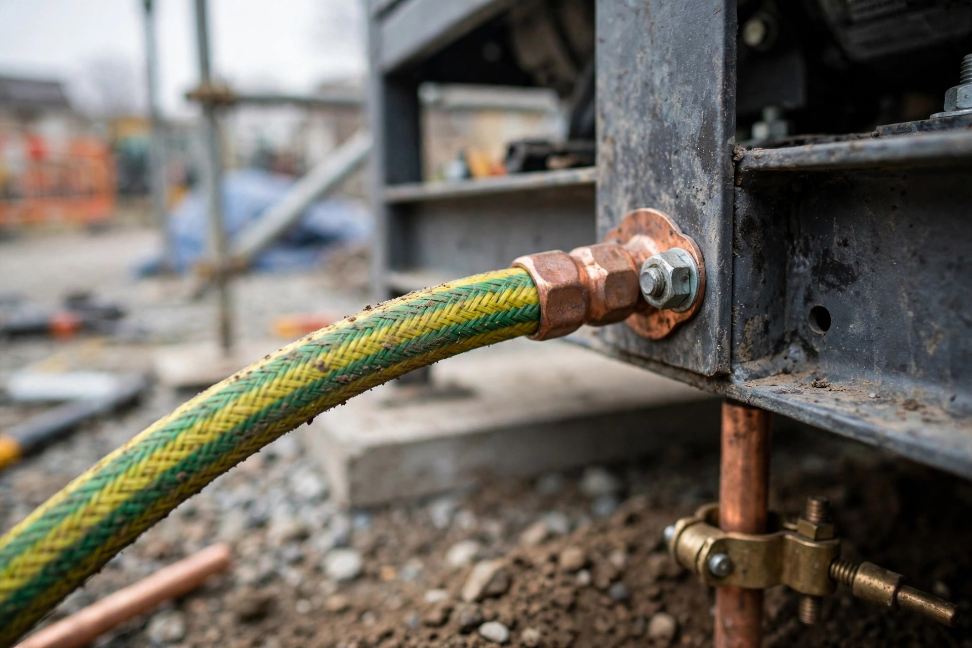
The standard temporary electrode is a copper-clad steel rod, 2.4 metres (8 feet) long and 16 mm in diameter, driven vertically into the ground until only the clamp is above the surface. The length matters because the top half-metre of soil dries out, freezes, or gets compacted by traffic, and contributes almost nothing to conductivity. The NEC requires a single rod to read 25 ohms or less; if it does not, a second electrode must be added. That 25-ohm figure is a code threshold, not a target — a rod reading 24 ohms passes the test and still leaves a TT system relying heavily on its RCD, which is exactly why the RCD must be there and must be tested.
Where one rod is not enough, the fix is more rods, not a longer hammer. Additional rods should be spaced at least one rod-length apart — 2.4 metres minimum, and further is better — because rods driven shoulder to shoulder share the same volume of soil and buy almost nothing. Two rods at proper spacing typically cut the resistance by 40 to 60 percent. Four rods in a square, bonded with bare copper, can bring a dry-site reading from 120 ohms down to 30. The connection between rods and the generator must be bare or green-yellow copper, sized to the fault current, and clamped with proper rod clamps, not wrapped wire and hope.
Soil and seasons: the number that moves
Soil resistivity decides everything, and it varies by two orders of magnitude between sites. The table below uses typical ranges; the only number that counts on a real site is the one the meter shows.
| Soil type | Resistivity (ohm-metres) | One 2.4 m rod, typical reading |
|---|---|---|
| Wet clay, marsh | 5–50 | 5–25 ohms |
| Moist loam, topsoil | 50–200 | 20–60 ohms |
| Dry sand, gravel | 200–1,000 | 80–200 ohms |
| Dry rock, broken concrete fill | 1,000–3,000 | 150–400 ohms |
The seasonal swing is the trap. A rod driven into moist loam in April reads 25 ohms. The same rod in August, after the water table drops and the top metre dries out, reads 80. The generator grounding guide records the extreme version: an eight-foot rod in dry sand reading 200 ohms. A 200-ohm electrode on a TT system still works with a 30 mA RCD — 200 × 0.03 is 6 volts, well inside the 50-volt limit — but it is a warning that the electrode is doing almost nothing and the RCD is doing everything. Test the rod in the dry season, not just the wet one, and write the reading down with the date.
Plates, mats and the Ufer option
Where a rod cannot be driven — rock, a concrete slab, a site where the set sits on a steel deck — the alternatives are a ground plate, a ground mat, or the foundation rebar. A copper plate of 600 × 600 mm, buried at least 600 mm deep in a bed of bentonite or conductive backfill, gives a large contact area and works well in shallow soil. A ring of bare copper tape around the generator plinth, bonded to the set and to the distribution board, spreads the fault current over a wide area and flattens the voltage gradient underfoot — the same principle substations use, scaled down to a site. Bentonite backfill, at roughly $40–$60 per 25 kg bag, can halve a rod’s resistance in dry ground and is cheap insurance on a rocky site.
The best electrode on any site is the one that costs nothing: the foundation rebar. A concrete-encased electrode, the Ufer ground, beats a driven rod in dry ground every time, because concrete holds moisture and contacts a large volume of soil. The catch is timing. The connection to the rebar has to be made before the concrete is poured, which means thinking about earthing on day one of the project instead of day thirty, when the set arrives and the rebar is already buried. For a generator that will serve a building for years after the site closes, that early decision is worth more than any rod.
The Neutral Bond on a Moving Set
If the electrode is the part of the system you can see, the neutral bond is the part you cannot — and the part that causes the most expensive mistakes. The rule is one sentence long: one bond, one place. The neutral connects to earth at exactly one point in the system. Every problem in this section is a violation of that sentence.
Separately derived, or not
A generator feeding a site on its own is a separately derived source. Its neutral is bonded to its frame and to its electrode at the set, and that bond is the single reference point for the whole installation. The bond is what makes a fault trip a breaker: without it, a live conductor touching the frame has no low-impedance path back to the source, and the frame simply sits energised.
The confusion starts when the site also has a mains supply. If the generator feeds the site through a transfer switch and the mains neutral is already earthed at the service entrance, bonding the generator neutral as well creates a second parallel path. Neutral current splits between the neutral conductor and the earth conductors, ground-fault protection sees current it was not designed for, and breakers trip for no apparent reason. One hospital data-centre project chased phantom ground faults for a week before someone drew the whole neutral path on a whiteboard and found the second bond. The fix was a drawing, not a part.
Three-pole or four-pole: the switch decides
The choice is made in the automatic transfer switch, and it has to match the bonding decision. A four-pole switch breaks the neutral as well as the three phases, so the generator’s bond is disconnected from the installation whenever the mains supply is running, and the mains bond is the only one in circuit. A three-pole switch leaves the neutral continuous, so any bond at the generator stays in circuit permanently — which is correct only if the generator is the only bonded source in the system.
The wrong combination is common on construction sites because the switch is often specified by someone who never saw the generator, and the generator is often delivered by someone who never saw the switch. A three-pole switch with a bonded generator on a site that also has a mains supply gives two bonds. A four-pole switch with a floating-neutral generator gives no bond at all when the generator is running, and a first fault that trips nothing. Either way the error is invisible until the fault happens. The check takes five minutes with a meter and a drawing: confirm where the single bond is, in each switch position, and write it on the inside of the transfer-switch door.
Two sets in parallel: still one bond
When a site grows and a second set is added, the bond rule does not relax — it gets stricter. Two generators running in parallel need one bond between them, not two. Two bonds create a loop between the sets, and the third-harmonic voltage that a three-phase alternator always produces at its star point drives a circulating neutral current around that loop. The current heats conductors, confuses ground-fault relays, and on one site PAVO engineers visited, it tripped the paralleling breaker every time the second set synchronised. The fix was a single neutral-earth link at the common busbar and a disconnect switch in each set’s earth lead, so the bond could be proved with both sets running and sharing load — not with the plant dead, when the circulating current conveniently disappears. The growth question — whether to parallel two generators or buy one larger set — is a sizing decision; the bond is a safety decision, and it is made the same way in both cases.
RCD Protection and the 110 V Rule
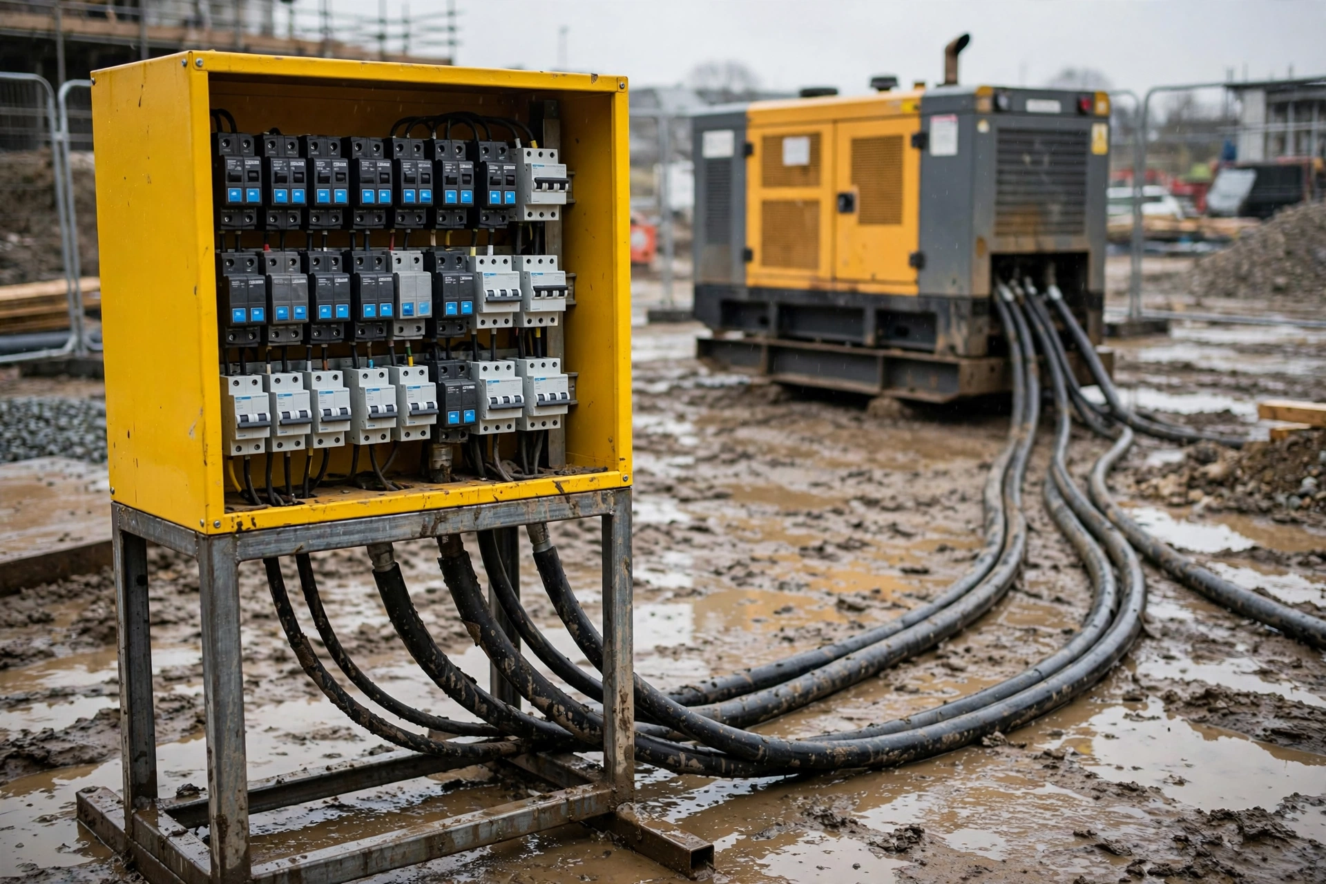
On a construction site the RCD is not an accessory. It is the protection. In a TT system it is the only device that can clear a fault to earth, because the fault current through soil is too small for a breaker. In a TN-S system it is the backup that catches the fault when the protective conductor has been damaged. Either way, the site’s safety depends on devices that are cheap, testable, and routinely ignored.
30 mA for sockets, 500 mA above 32 A
BS 7671 Section 704 sets the numbers. Every socket-outlet circuit rated up to and including 32 A must be protected by a 30 mA RCD (Regulation 704.410.3.10, under Regulation 415.1.1). Socket circuits above 32 A need an RCD with a rated residual operating current not exceeding 500 mA (Regulation 704.411.3.2.1). The 30 mA figure is chosen because it is below the threshold where current through the body causes ventricular fibrillation; the device must trip within 40 milliseconds at its rated current, and within 300 milliseconds at five times rated current. A 30 mA RCD on a site distribution board costs $25–$60 for a single-phase unit and $80–$150 for a three-phase unit. A life is not in the same price range.
The test button is part of the device, not decoration. It should be pressed monthly at minimum, and on a construction site weekly is the honest interval — dust, vibration and moisture kill RCDs faster than age does. On larger sites the RCD trip contacts and earth-fault alarms can be wired into the site’s remote monitoring system, so a tripped board on the far side of the site raises an alarm in the office instead of waiting for someone to walk over. A board whose RCD test buttons have never been pressed is a board whose protection is assumed, and assumptions are what this article is about.
The wrong RCD type: AC, A, or B
Not every RCD trips on every fault. A Type AC RCD responds only to sinusoidal alternating residual current. A Type A adds pulsating DC. A Type B responds to smooth DC as well, and to high-frequency leakage. BS 7671 Amendment 2, Regulation 531.3.3, states that Type AC shall only be used to serve fixed equipment where it is known that the load current contains no DC components — and on a construction site, that condition almost never holds. Three-phase loads with inverters — tower-crane drives, pumps, compressors, welders, battery chargers — produce smooth DC leakage currents that can blind a Type AC or Type A RCD, leaving it unable to trip when a real fault arrives. The German implementation of the same standard requires Type B RCDs on all three-phase sockets up to 63 A on construction sites.
A three-phase Type B RCD costs $150–$400, roughly three times a Type AC unit. That premium is the entire cost of the protection against the fault that a Type AC device cannot see. When a site buys a distribution board, the RCD type is a line on the specification, not a detail to discover after the crane drive is connected.
110 V centre-tapped earth: the tool voltage
Portable hand tools and handlamps on UK construction sites run on 110 V reduced low voltage — a 55-0-55 V centre-tapped-earth arrangement in which no live conductor sits more than 55 V above earth (BS 7671 Regulation 411.8.1.2). Disconnection must occur within 5 seconds at every point of utilisation, including socket-outlets (Regulation 411.8.3). The 110 V transformer, typically 3 kVA or 5 kVA and costing $300–$600, is fed from the generator or the site supply and sits between the 230 V world and the worker’s hands. It is not a convenience; it is the reason a damaged drill cable on a wet site gives a shock instead of a funeral.
Site distribution assemblies themselves must comply with BS EN 61439-4 as Assemblies for Construction Sites, with switching and isolating devices that can be secured in the off position. That applies equally whether the source is a transformer or a mobile generator feeding the board. And the surge protection at the transfer switch, which the surge guide on this site covers in detail, belongs in the same conversation: the grounding system and the surge devices are a team, and neither finishes the job alone.
| Circuit | Protection required | Regulation |
|---|---|---|
| Socket outlets up to 32 A | 30 mA RCD | BS 7671 704.410.3.10 / 415.1.1 |
| Socket outlets above 32 A | 500 mA RCD max | BS 7671 704.411.3.2.1 |
| Three-phase sockets with inverter loads | Type B RCD | BS 7671 531.3.3 (Amd 2) |
| Portable tools and handlamps (UK) | 110 V CTE, 55 V to earth, 5 s disconnection | BS 7671 411.8.1.2 / 411.8.3 |
| Temporary installation inspection | Every 3 months | BS 7375:2010 |
Three Sites That Got It Wrong — and What It Cost
Case 1: The floating set and the welder in Lagos
A high-rise residential project in Lagos ran a 200 kVA rental set — a Cummins-powered silent unit, 160 kW prime — feeding a site board that served a tower crane, two welders and a cabin block. The set arrived with a floating neutral, the factory default. Nobody checked. The site electrician, who arrived three days after the set, found the board wired and the crane already lifting.
On the second week a welder resting his electrode holder against the crane mast felt a shock through wet gloves. The investigation found a damaged cable on the welder’s return lead, a frame that had drifted to 140 V above earth, and a fault that no breaker had seen because there was no bond and no RCD on the welder’s circuit. The fix took one morning: bond the neutral at the set, drive a 2.4 m rod that tested 38 ohms in the dry-season soil, fit a 30 mA Type B RCD on each socket circuit, and re-test. Cost of the fix: roughly $1,800 in parts and labour. Cost of the shock: a hospital visit, a day’s lost production, and a project manager who now checks the neutral link before the first lift. The set itself was never the problem. The set was fine. The earthing was a guess.
Case 2: The PME supply exported to a housing site in England
A housing development of 42 units in the English Midlands took its temporary supply from the PME terminal of the neighbouring completed phase and extended it to the site cabins and the tower crane. The arrangement worked for four months. Then a contractor excavating a service trench cut the PEN conductor. The cabins’ steel frames rose toward line voltage. A worker touching a cabin door and a scaffold tube at the same time received a shock that put him in hospital, and the Health and Safety Executive served a prohibition notice that stopped the site for six days.
The investigation was short. BS 7671 Regulation 704.411.3.1 prohibits PME on construction sites unless every extraneous conductive part is reliably bonded to the main earthing terminal, and on a site of scaffolding, temporary cabins and open trenches that condition could not be met. The remedy was to convert the whole site to TT: a 250 kVA generator with its own electrode, 30 mA RCDs on every socket circuit, and a written earthing drawing taped inside every board. The six-day stoppage cost the developer roughly £48,000 in delay and standing time. The electrode and RCDs cost under £2,000. The regulation had been in the book the whole time.
Case 3: The set that moved three times in a quarry in Western Australia
A quarry in Western Australia ran a 500 kVA set rated for standby and prime power duty that moved with the crushing plant: three positions in six months, each move a full day’s work with a low-loader. The earth rod stayed behind at the first position. At the second position a new rod was driven and tested at 22 ohms. At the third position the crew, under pressure to restart crushing, connected the set and started it without driving a rod at all — the ground wire was coiled neatly beside the set, still attached to the frame at one end and to nothing at the other. It stayed that way for eleven weeks, through the dry season, until a quarterly inspection found it.
Nothing happened in those eleven weeks. That is the point. A missing earth on a generator does not announce itself. The set ran, the crusher crushed, the voltage was steady, and the only evidence was a coil of green-yellow cable and an inspection sheet with a blank line. The fix was procedural, not technical: an earth kit — rod, clamp, 25 metres of 16 mm² cable and a test log — now travels in a locked box bolted to the set’s trailer, and the set does not start until the log shows a reading for the current position. The kit costs $320. The eleven weeks of unprotected operation cost nothing, which is exactly why it is the most dangerous case in this article.
Frequently Asked Questions
How do you ground a generator on a construction site?
Bond the neutral to earth at one point on the set, drive a temporary electrode — usually a 2.4 m copper-clad rod — at the generator, connect the frame and every distribution board to that electrode, and protect every socket circuit with a 30 mA RCD. Then test the electrode resistance and the RCD trip time every time the set moves, and record the readings with the date.
What is the difference between TT and TN-S earthing system?
In a TT system the fault current returns through the soil between a local electrode at the load and the electrode at the source, so protection depends on an RCD. In a TN-S system the fault current returns along a separate protective conductor in the cable, the loop impedance is low, and an ordinary breaker clears the fault. A standalone generator site is normally TT; a site wired with proper five-core cable to a bonded source can be TN-S.
Do I need an earth rod for a generator on a construction site?
Yes, unless the generator is feeding only its own outlets through GFCI protection as a portable set. Any generator feeding a site distribution board, a crane, cabins or fixed equipment needs its own electrode at the set, and the site needs its own electrode at the board. A generator with no electrode and a floating neutral leaves a first fault invisible and a second fault dangerous.
What size earth rod do I need for a diesel generator?
The standard is a copper-clad steel rod 2.4 metres (8 feet) long and 16 mm in diameter, driven vertically until only the clamp shows. The NEC requires a single rod to read 25 ohms or less; if it reads more, add a second rod at least one rod-length away. In rocky or dry ground, use multiple rods, a ground plate, or bentonite backfill rather than a longer rod.
Does a generator need RCD protection on a construction site?
Yes. On a TT site the RCD is the only device that can clear an earth fault, because fault current through soil is too small to trip a breaker. BS 7671 Section 704 requires 30 mA RCD protection on socket circuits up to 32 A and 500 mA above that, and Type B RCDs where inverter-driven equipment is connected. Test the RCDs weekly on a working site, not monthly.
Specification Checklist: Ten Questions Before the Set Arrives
- Where is the single neutral-earth bond? Written down, on the drawing, and confirmed in each transfer-switch position.
- What earthing system is the site? TT, TN-S or TN-C-S — named, not assumed. If the answer is PME, convert to TT before the first lift.
- Is the electrode at the set, and what did it read? A 2.4 m rod, a reading in ohms, and a date. No reading, no start.
- Is there an electrode at the distribution board? The board needs its own earth, not a borrowed one from the building.
- Are the RCDs the right type? 30 mA up to 32 A, 500 mA above, Type B where inverters, welders or crane drives are connected.
- Are the tools on 110 V? Centre-tapped earth, 55 V maximum to earth, transformer sized for the load.
- Does the earth travel with the set? Rod, clamp, cable and test log in a box on the trailer, so a move never leaves the earth behind.
- Who tests, and how often? Earth resistance and RCD trip time at every move, and a full inspection every three months.
- Is the ground wire still there? Copper theft and “temporary” removal are the two commonest causes of a missing earth. Check after every service visit.
- What spares are on site? A spare rod, spare clamps, a spare 30 mA RCD and a reel of green-yellow cable belong in the site store alongside the filters and belts. The spare parts list for a generator should include earthing consumables, because the day the RCD fails is the day the site has no protection.
A generator’s earthing is the cheapest part of the installation and the hardest part to fix later, once the concrete is poured and the set is running. The rod costs less than a tank of fuel. The RCD costs less than a day’s hire. The test takes twenty minutes. The alternative is a site where the first fault is invisible and the second one is the one that gets remembered. If the earthing design for a site is still an open question, or if a set is about to move to a new position and nobody has checked the electrode, contact PAVO — a second pair of eyes on the drawing before the concrete goes in is cheap insurance, and it is a lot cheaper than a prohibition notice.