

What Size Generator Does a Chemical Plant Need? | PAVO
A chemical plant does not stop when the power fails. It keeps reacting — in vessels full of hot, pressurised, sometimes unstable material, with no operator able to press pause. The generator is what stands between a ten-second outage and a runaway reaction.
What size generator does a chemical plant need? A batch plant needs 250–500 kVA for its essential board, a mid-size continuous plant needs 1,000–2,000 kVA, and a large petrochemical site needs 2,000–3,750 kVA or several sets in parallel. The set never powers the whole plant — it powers the safety systems and the loads that keep a reaction under control.
Contents
- Why a Chemical Plant Is Not Like Any Other Load
- What the Generator Actually Has to Carry
- Sizing the Set: What Size Generator Does a Chemical Plant Need?
- The First 10 Seconds and the Next 10 Minutes
- Hazardous Areas, Corrosion and Where the Generator Can Sit
- Three Plants That Learned the Hard Way
- Frequently Asked Questions
- Specification Checklist: Before You Sign the Order
Why a Chemical Plant Is Not Like Any Other Load
Most factories lose an hour of production when the grid fails. A chemical plant can lose the plant. The difference is that a chemical process does not stop when the electricity stops. An exothermic reaction keeps generating heat whether the cooling water pump is running or not. A batch of organic peroxide keeps warming in its warehouse whether the refrigeration compressor has power or not. Molten sulphur, molten polymer and hot caustic keep cooling, thickening and solidifying in pipes and vessels that were never designed to be reheated from cold.
That is the first fact a generator buyer in this sector has to accept. The generator is not buying production time. It is buying control. Control of temperature, control of pressure, control of agitation, control of the flare and the scrubber that keep whatever escapes from reaching people outside the fence. Everything else — keeping a line running, finishing a batch, saving a shift’s output — is secondary.
The money explains why the sector treats backup power as a safety system rather than a convenience. ABB’s 2023 survey of 3,215 industrial businesses put the median cost of an hour of unplanned downtime at $124,669. Its 2025 survey put the range at $10,000 to $500,000 per hour, and chemicals and oil and gas sit at $15,000 to $40,000 per hour in the Aberdeen Group and IndustryWeek benchmarks. Those figures count lost production. They do not count the cost of a batch that has to be scrapped because it went out of specification, the cost of a vessel that has to be cut open because product solidified inside it, or the cost of a release that puts a plant on the evening news. In a chemical plant, the cost curve is not linear. The first ten minutes are cheap. The first hour is expensive. The second day is a different order of magnitude, because by then the plant is not restarting — it is recovering.
The second fact is that a chemical plant’s electrical load is not one load. It is three loads that happen to share a switchboard. There is the safety load, which must never stop. There is the process load, which decides whether the plant rides through or shuts down safely. And there is the general load — offices, workshops, non-essential lighting — which can be dropped without consequence. A generator sized for the whole plant is a generator nobody can afford and nobody needs. A generator sized for the essential board is a generator that earns its keep in the first outage.
The third fact is the environment. A chemical plant is one of the few places where the generator itself can be the hazard. Diesel engines produce hot exhaust, sparking alternators and fuel vapour. Chemical plants contain flammable gases, vapours and dusts. The two have to be kept apart by distance, by enclosure and by rules that are written into law in most countries. A buyer who treats a chemical plant like a warehouse with bigger motors will get the sizing right and the placement wrong, and the placement is the part that can shut the plant down permanently.
What the Generator Actually Has to Carry
The essential board of a chemical plant is built in tiers, and the tiers decide the generator size, the transfer scheme and the fuel autonomy. A tier that is left off the board is a tier that fails in the first outage. The tiers below are the ones used in practice on batch and continuous plants from 250 kVA to 3,750 kVA.
Tier 1 — Safety systems that must never stop
The safety instrumented system, the fire and gas detection system, emergency lighting, the flare knock-out drum pumps, the scrubber circulation pumps, the control room UPS and the emergency ventilation all sit in Tier 1. These loads are small — typically 30–150 kW on a mid-size plant — but they are non-negotiable. The safety instrumented system trips the plant to a safe state when a parameter goes out of range, and it can only do that while it has power. The flare system burns off vented gas, and its knock-out pumps and ignition system need power to do it. The scrubber keeps a release from leaving the site, and its circulation pumps are the difference between a contained incident and a community evacuation.
Tier 1 loads run on the UPS for the seconds between grid failure and generator start, and on the generator after that. The UPS is sized in minutes, not hours. A 10-second generator start is the standard for these systems under NFPA 110 Level 1, and the UPS bridges that gap. A generator that takes 30 seconds to accept load is a generator that has already failed Tier 1, even if it starts perfectly.
Tier 2 — Process continuity: the loads that keep a reaction under control
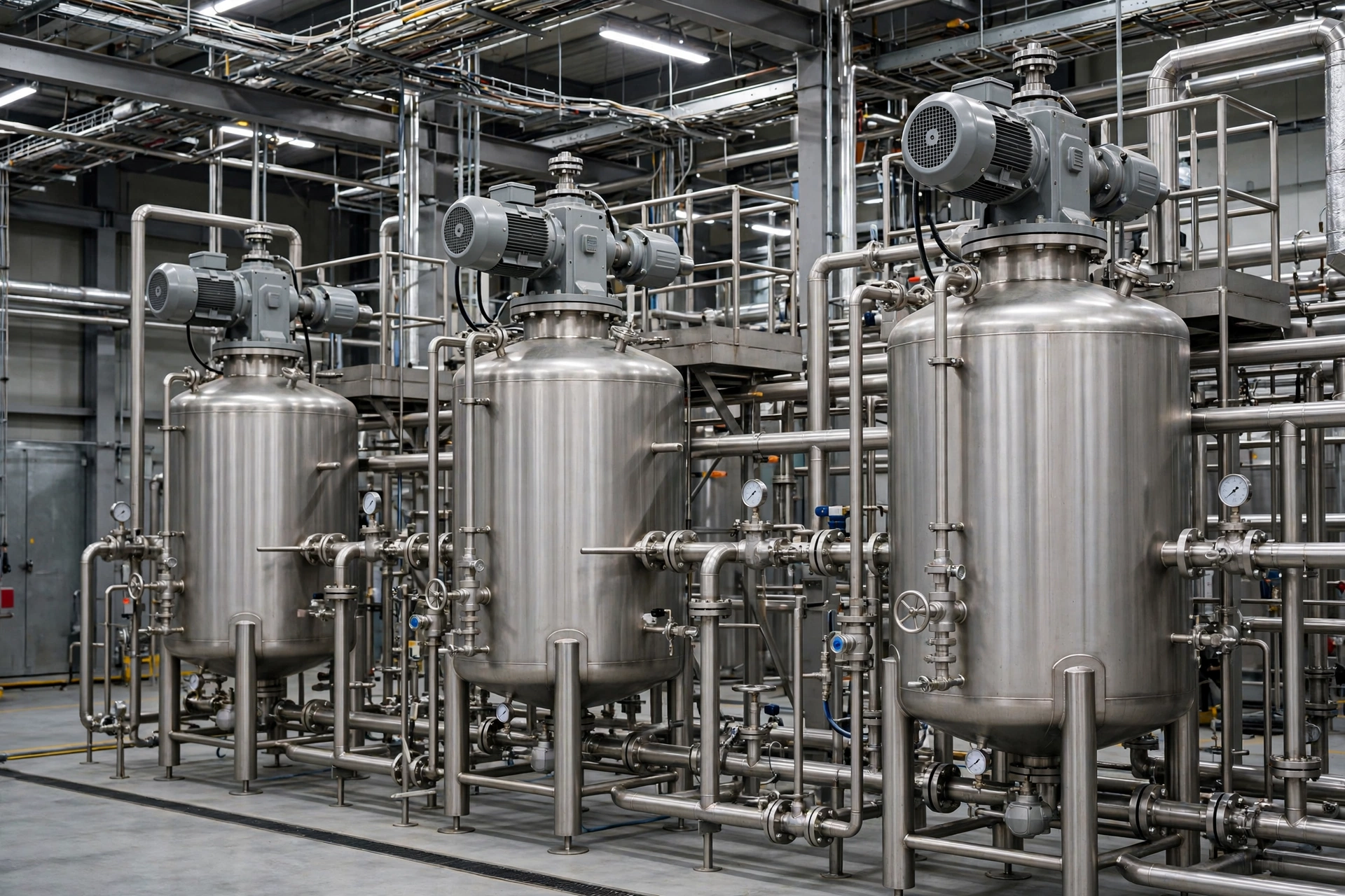
Agitator motors, cooling water pumps, refrigeration compressors, nitrogen supply, instrument air compressors and the distributed control system sit in Tier 2. These are the loads that decide whether the plant rides through the outage or shuts down. An agitator motor on a 10 m³ reactor typically draws 15–30 kW; a 20 m³ reactor takes 30–75 kW. Cooling water pumps run 22–110 kW each. Refrigeration compressors for cold storage of temperature-sensitive product run 30–200 kW. Instrument air compressors run 15–75 kW.
Tier 2 is where the sizing work happens. The motors are large, they start with a surge, and they start at the same time if the transfer scheme is not sequenced. A 110 kW pump started direct-on-line draws six times its running current — roughly 660 kVA of starting demand for a few seconds. Three such pumps starting together will collapse the voltage on a set that was sized only for running load. Sequenced starting, soft starters and variable-speed drives change the arithmetic completely, and the motor starting guide covers the methods in detail. The rule for a chemical plant is simple: the generator is sized for the largest motor start plus the running load already on the board, never for running load alone.
Tier 3 — Restart and utilities: the loads that decide how fast the plant comes back
Effluent treatment aeration blowers, raw water pumps, air compressors for general use, workshop power, cranes and non-essential lighting sit in Tier 3. These loads can wait an hour. They cannot wait a week. Effluent treatment is the one that catches buyers out. Aeration blowers run 30–90 kW, and if they stop, the biological treatment in the effluent plant starts to die. Re-seeding a dead biological treatment system takes 24–48 hours at best, and during that time the plant cannot discharge effluent legally. A plant that restarts its reactors in six hours and its effluent plant in three days has not restarted at all.
The essential board — Tiers 1 and 2, plus the Tier 3 loads that cannot wait — is typically 10–25% of the plant’s total connected load. A specialty batch plant with 3 MVA of total load usually carries an essential board of 300–600 kVA. A mid-size continuous plant with 10 MVA of total load carries 1,000–2,000 kVA. A petrochemical complex with 50–200 MVA of total load carries an essential board of 2,000–3,750 kVA or several sets in parallel, and even then the set covers the safety and control loads, never the crackers or the furnaces.
Sizing the Set: What Size Generator Does a Chemical Plant Need?
Sizing starts with a load list, not a catalogue. The load list records every load on the essential board, its running kW, its starting method and its starting kVA. The generator is then sized for the running load plus the largest single starting transient, with a 15–20% margin for load growth and for the voltage dip limit. The generator sizing guide covers the full method; the table below gives the bands that experienced buyers use as a first check.
| Plant type | Total plant load | Essential board | Recommended set | Fuel at 75% load |
|---|---|---|---|---|
| Specialty batch, resins / adhesives | 1–3 MVA | 250–500 kVA | 250–500 kVA, single set | 32–63 L/h |
| Mid-size continuous, coatings / agrochemicals | 5–12 MVA | 800–1,500 kVA | 1,000–1,500 kVA, single set | 126–190 L/h |
| Large continuous, petrochemical / fertiliser | 20–60 MVA | 2,000–3,000 kVA | 2 × 1,500 kVA or 1 × 3,000 kVA | 250–380 L/h |
| Petrochemical complex, crackers / refineries | 50–200 MVA | 3,000–6,000 kVA | 2–3 × 2,000 kVA in parallel, 11 kV | 380–750 L/h |
Fuel figures use the standard rule of thumb of 0.21 litres per kWh generated. A 500 kVA set (400 kW) at 75% load produces 300 kW and burns about 63 L/h. A 1,000 kVA set (800 kW) at 75% load burns about 126 L/h. A 2,000 kVA set (1,600 kW) at 75% load burns about 252 L/h. The Cummins C500D5 datasheet gives a measured figure for the same frame: 500 kVA standby / 455 kVA prime, 93.2 L/h at prime full load. Real consumption is always lower than the catalogue figure at part load, and always higher than the buyer hoped at full load. Size the tank on the measured figure, not the brochure figure.
A worked example makes the method concrete. A specialty resin plant in western India runs a 3 MVA total load. Its essential board carries two 30 kW agitators, one 75 kW cooling water pump, one 55 kW refrigeration compressor, one 37 kW instrument air compressor, 40 kW of safety systems and lighting, and 30 kW of effluent aeration — 297 kW of running load, or about 370 kVA at 0.8 power factor. The largest single start is the 75 kW cooling water pump, started direct-on-line at six times running current, about 560 kVA of starting demand for two seconds. Running load minus that pump plus the starting transient gives 370 − 94 + 560 = 836 kVA of transient demand. A 1,000 kVA set handles it with margin. A 500 kVA set does not — the voltage dip would trip the control system and drop the load it was bought to protect. The plant ordered the 1,000 kVA set. That is the arithmetic that decides whether a generator works on the day it matters.
How long the set can run
Fuel autonomy is the second half of sizing, and it is where chemical plants differ from every other sector. A hotel or a supermarket needs 8–24 hours of fuel. A chemical plant needs fuel for the whole outage plus the restart, and the restart can take longer than the outage. A continuous plant that trips takes 12–72 hours to restart safely: vessels have to be checked, catalysts have to be reactivated, product has to be brought back into specification. The generator has to be running for all of it, or the plant has to be shut down in a controlled way and the generator has to be running for that instead.
| Set size | Fuel burn at 75% load | 8 hours | 24 hours | 72 hours |
|---|---|---|---|---|
| 250 kVA | 32 L/h | 256 L | 768 L | 2,304 L |
| 500 kVA | 63 L/h | 504 L | 1,512 L | 4,536 L |
| 1,000 kVA | 126 L/h | 1,008 L | 3,024 L | 9,072 L |
| 2,000 kVA | 252 L/h | 2,016 L | 6,048 L | 18,144 L |
A 1,000 kVA set needs a 10,000-litre bulk tank for 72 hours of autonomy, and a 2,000 kVA set needs 20,000 litres. Those are bulk tanks with transfer pumps, bunding and level alarms, not the sub-base tank the set ships with. A sub-base tank of 500–1,000 litres gives a 1,000 kVA set four to eight hours. That is enough to ride through a short outage. It is not enough to ride through a storm that takes the grid down for three days. Diesel fuel ageing matters here too: fuel that sits in a bulk tank for a year without testing and polishing is fuel that will block a filter at hour 30 of a 72-hour outage.
The rating matters as much as the tank. A standby-rated set is limited by ISO 8528-1 to an average of 200 hours per year and a maximum of 500 hours per year, with no overload allowed. A prime-rated set can run unlimited hours at variable load, with a 10% overload available for one hour in twelve. A plant that expects a 72-hour outage once a year and a handful of shorter outages is inside the standby limit. A plant in a region with an unreliable grid, running its generator 500 hours a year or more, needs a prime rating. The standby and prime power ratings article explains the distinction in full, and it is the single most common sizing mistake in this sector: buying a standby set for a prime duty and then discovering the warranty does not cover the hours.
The First 10 Seconds and the Next 10 Minutes
The first ten seconds decide whether the safety systems survive. The next ten minutes decide whether the process survives. The two windows need different equipment, and a buyer who confuses them ends up with a generator that starts on time and a plant that still trips.
The ten-second window belongs to NFPA 110. Level 1 emergency power systems — the systems that protect life safety — must start and accept load within 10 seconds of grid failure. The automatic transfer switch senses the failure, signals the generator to crank, and transfers the essential board to generator power. A modern diesel set reaches rated speed and voltage in 8–10 seconds from the crank signal, which is why the 10-second rule is written the way it is: it is the time a well-maintained diesel set actually needs. A set with a weak battery, a cold engine or a clogged fuel filter takes 15 seconds, and those five seconds are the difference between a UPS that bridges the gap and a control system that reboots mid-trip.
The ten-minute window belongs to the process. Every chemical process has a damage window — the time between loss of cooling, agitation or refrigeration and irreversible damage. The table below gives the windows that matter when a buyer writes the load-shedding sequence.
| Process | What fails first | Damage window | Consequence if missed |
|---|---|---|---|
| Organic peroxide cold storage | Refrigeration | Hours to days | Self-accelerating decomposition, fire |
| Exothermic batch reaction | Agitation and cooling | Minutes to tens of minutes | Runaway reaction, pressure relief, venting |
| Molten sulphur / polymer lines | Trace heating and pumps | 30 minutes to 2 hours | Solidification in pipes and vessels |
| Crystallisation | Agitation and temperature control | 1–4 hours | Off-specification crystal, batch scrapped |
| Refrigerated product storage | Refrigeration compressors | 4–12 hours | Product warms out of specification |
| Effluent biological treatment | Aeration blowers | 24–48 hours | Biology dies, discharge consent breached |
The windows explain why the transfer sequence matters more than the generator size. The agitators and the cooling water pumps transfer first, in the first minute. The refrigeration compressors transfer next, sequenced one at a time so their starting surges do not stack. The effluent blowers transfer last, because they have a 24-hour window and the generator has a finite capacity. A plant that transfers everything at once overloads the set, trips the breaker and loses the lot. A plant that sequences its loads rides through an outage that would have shut it down.
The UPS deserves a sentence of its own. The distributed control system, the safety instrumented system and the fire and gas system run on UPS power for the seconds between grid failure and generator start, and for the minutes it takes to confirm the generator is stable. A UPS sized for 15–30 minutes is standard. A UPS sized for 5 minutes is a UPS that has already failed when the generator takes 12 seconds to start and the operator takes 10 minutes to confirm the transfer. Size the UPS for the operator, not for the generator.
Hazardous Areas, Corrosion and Where the Generator Can Sit
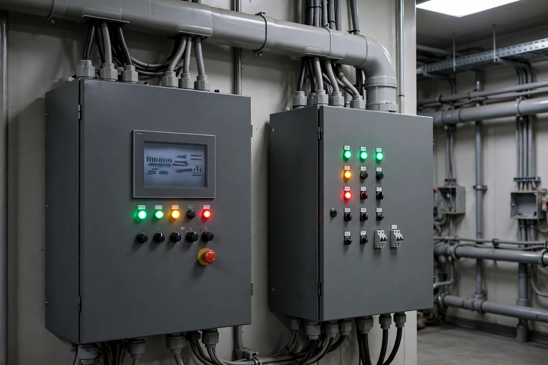
A diesel generator is an ignition source. It has a hot exhaust manifold at 400–600°C, a sparking alternator, a fuel system under pressure and a battery that can gas hydrogen. A chemical plant contains flammable gases, vapours and dusts. The two are kept apart by area classification, and the classification is law, not guidance.
IEC 60079-10-1 divides a plant into zones. Zone 0 is an area where an explosive atmosphere is present continuously or for long periods. Zone 1 is an area where an explosive atmosphere is likely to occur in normal operation. Zone 2 is an area where an explosive atmosphere is not likely to occur in normal operation, and if it does, it persists for a short period only. Equipment installed in each zone must carry the matching ATEX category: 1G for Zone 0, 2G for Zone 1, 3G for Zone 2. A standard diesel generator set carries no ATEX category. It cannot be installed in Zone 1 or Zone 2. It is installed in a safe area, outside the classified zones, and the power is cabled in.
The distance is decided by the plant’s hazardous-area drawing, and it is typically 15–30 metres from the classified area boundary for a standard set. That distance costs money: longer cable runs, larger cable sizes, a separate generator building or a containerised set on a plinth. It also costs time in design, because the hazardous-area drawing has to be produced before the generator position is fixed, not after. The hazardous-area rules for petrol stations article covers the same zone logic applied to a forecourt, and the principles are identical: the generator sits outside the zones, the fuel is stored outside the zones, and the transfer switch is the only item that crosses the boundary, in an approved enclosure.
Corrosion is the second placement problem, and it is the one that kills generators slowly rather than suddenly. Chlorine, hydrogen chloride vapour, sulphur compounds and ammonia attack steel, copper and electronics. A generator installed downwind of a chlor-alkali plant or a sulphuric acid unit will show the damage in a year: rust on the canopy, green corrosion on the alternator windings, failed sensors and a control panel that stops responding. The countermeasures are unglamorous and effective. A C5-rated coating on the canopy instead of the standard C3. Stainless steel fasteners and hinges. A chemical filter on the alternator cooling air intake. A control panel sealed to IP55 with the electronics in a separate, filtered compartment. And a maintenance schedule that inspects for corrosion every quarter instead of every year, because in a chemical plant a year is long enough for a small leak to become a failed winding.
Heat and dust complete the picture. A chemical plant is a hot place: steam lines, hot vessels and exothermic reactions raise the ambient temperature around the generator building, and a generator that was rated at 25°C loses roughly 1% of its output for every 5°C above 40°C on the alternator, more on the engine. A set installed in a 45°C enclosure without ventilation derates by 10–15% before it has carried a single load. The radiator needs clean air, the enclosure needs louvres sized for the full heat rejection, and the air intake needs to be upwind of the dusty operations — bagging lines, powder handling and solid raw material unloading all produce dust that blocks a radiator in weeks.
Three Plants That Learned the Hard Way
Arkema Crosby, Texas — the generators that drowned
The most instructive generator failure in the chemical industry happened in August 2017, at the Arkema organic peroxide plant in Crosby, Texas, during Hurricane Harvey. The plant manufactured 30 different organic peroxides, stored in seven electrically powered cold-storage warehouses held at about −18°C. Organic peroxides decompose when they warm up, and the decomposition accelerates as the temperature rises — a self-accelerating reaction that ends in fire.
The plant sat in the 100-year floodplain, a fact recorded on flood maps since 2007. Its backup generators sat two feet above ground. When Harvey dropped 60 inches (1.5 metres) of rain on the Texas Gulf Coast, the floodwater rose past the generators. Commercial power was lost at about 2 a.m. on 27 August, when the transformers flooded. Two standby generators started and carried the last cold-storage warehouse. One flooded within hours. At 3 a.m. the ride-out crew began moving product into refrigerated trailers, fearing the loss of the last generator. At 5 a.m. the crew switched the last generator off. The liquid nitrogen backup system failed when its piping submerged.
Over the next three days, more than 350,000 pounds of organic peroxide burned in three fires — 31 August, 1 September, and a controlled burn on 3 September. A 1.5-mile evacuation zone displaced more than 200 residents for a week. Twenty-one emergency responders sought medical attention after exposure to fumes. There were no fatalities, which the U.S. Chemical Safety Board’s final report in May 2018 attributed to the evacuation, not to the plant’s defences. The Board’s conclusion was blunt: all layers of protection failed from a single common cause — flooding — and none of the safeguards against electrical failure met industry standards.
The lesson for a generator buyer is not that Arkema should have bought a bigger set. It is that the set was in the wrong place. A generator two feet above ground in a 100-year floodplain is a generator that will drown in the same flood that takes the grid. Elevation, separation and a genuinely independent backup — a second set on high ground, a nitrogen system that does not share the flood exposure — are the design decisions that matter. The generator worked. The site around it did not.
The Texas freeze, February 2021 — the grid that failed a whole sector
Four years later, the same coast failed in the opposite weather. In February 2021, a polar storm brought temperatures of −8°C to Houston, a city built for heat. Thirty-four gigawatts of generation went out of service, 20 GW of it thermal. Rolling blackouts swept the state. The chemical sector, which had spent decades hardening against hurricanes, discovered it had not hardened against cold.
By 23 February, about 75% of total U.S. ethylene capacity was offline, according to Vertical Research Partners. Sixty-one percent of U.S. ethylene capacity and 59% of propylene capacity were shut down. Dow declared force majeure on intermediate chemicals at Deer Park, Freeport, Texas City and Bayport. LyondellBasell shut down its 1.9 billion-pound-per-year olefins units at Channelview and its 2.6 billion-pound-per-year ethylene unit at La Porte. ExxonMobil shut down all units at Baytown. Chevron Phillips suspended its 2.3 billion-pound-per-year polyethylene plant at Pasadena. Flaring lit up the Houston skyline for a week as plants vented inventory they could not process.
The freeze did not produce a single Arkema-style fire, because the plants shut down in a controlled way and the cold itself slowed the chemistry. It produced something else: a demonstration that a chemical plant’s backup power has to be sized for the restart, not just for the outage. Plants that lost power for three days took one to three weeks to come back, because frozen instrument lines, cracked pipework and solidified product had to be found and repaired before a single reactor could restart. The generators that mattered in February 2021 were not the ones that kept a line running. They were the ones that kept the trace heating, the instrument air and the control systems alive so that the plant could be restarted at all — and the plants that had not put those loads on the essential board paid for it in weeks of lost production.
A resin plant in Ankleshwar, Gujarat — the set that earned its price
The third case is smaller, and it is the one most buyers will recognise. A specialty resin plant in Ankleshwar, Gujarat — India’s largest chemical estate, home to more than 1,000 chemical units — runs batch reactors for adhesives and coatings. Its total load is 3 MVA. Its essential board is 1,000 kVA: two 30 kW agitators, a 75 kW cooling water pump, a 55 kW refrigeration compressor, instrument air, safety systems and effluent aeration.
During the 2023 monsoon season, a feeder fault took the estate’s grid supply down for 14 hours. The plant’s 1,000 kVA Cummins set, installed on a raised plinth above the estate’s known flood level, started in 9 seconds and accepted the sequenced load in under two minutes. The agitators never stopped. The cooling water never stopped. Two batches worth roughly $45,000 in raw material stayed in specification. The set burned 63 L/h at 75% load — about 880 litres over the outage — from a 5,000-litre bulk tank that still held three days of fuel when the grid returned.
The plant’s neighbour, a coatings manufacturer of similar size, had a 500 kVA set that had never been load-tested. It started, took the agitators, and tripped on overload when the refrigeration compressor started thirty seconds later. The batch in the reactor solidified when the cooling water stopped, and the vessel had to be opened and cleaned by hand — three days of lost production and a $12,000 cleaning bill. The difference between the two plants was not the size of the set. It was a load list, a sequenced transfer and a monthly load test. The first plant’s generator cost $68,000 installed. It paid for itself in one night.
Frequently Asked Questions
What size generator does a chemical plant need?
A specialty batch plant needs 250–500 kVA for its essential board, a mid-size continuous plant needs 1,000–2,000 kVA, and a large petrochemical site needs 2,000–3,750 kVA or several sets in parallel. The set is sized from a load list — running load plus the largest single motor start, with a 15–20% margin — and it covers the safety systems and the loads that keep a reaction under control, never the whole plant.
Do chemical plants need a backup generator?
Yes, and in most jurisdictions the need is not optional. Safety systems, flare systems, scrubbers and the control system must stay live during a grid failure, and regulators under Seveso in Europe, COMAH in the UK and the EPA’s Risk Management Program in the United States all expect a plant to demonstrate that it can shut down safely or ride through without power. A plant without backup power is a plant whose safety case has a hole in it, and insurers price that hole accordingly.
How long can a chemical plant run on a generator?
As long as the fuel lasts and the rating allows. A 1,000 kVA set burns about 126 L/h at 75% load, so a 10,000-litre bulk tank gives about 72 hours. A standby-rated set is limited to an average of 200 hours per year and a maximum of 500 hours per year; a plant that expects longer outages needs a prime rating and a refuelling plan, because a 72-hour tank is useless if the fuel truck cannot reach the site.
What happens to a chemical plant during a power outage?
The automatic transfer switch starts the generator within 10 seconds and the essential board transfers in a sequenced order — agitators and cooling water first, refrigeration next, effluent last. If the generator holds, the plant either rides through or shuts down in a controlled way. If it does not hold, the damage windows decide the outcome: an exothermic batch can run away in minutes, molten product solidifies in hours, and a full restart after a cold trip takes 12–72 hours.
Can a diesel generator power a chemical plant?
A diesel generator can power the essential board of any chemical plant, from a 250 kVA batch plant to a multi-megawatt petrochemical complex running several sets in parallel. It cannot power the whole plant — a cracker or a furnace draws tens of megawatts — and it is not supposed to. The generator’s job is the safety systems, the cooling, the agitation and the control that keep the plant safe and restartable, and for that job a high-voltage generator is the right answer when the essential board passes 2,000 kVA.
Specification Checklist: Before You Sign the Order
A chemical plant generator is specified once and lived with for twenty years. The checklist below is the difference between a set that works on the day it matters and a set that becomes a very expensive ornament.
- Load list first. Every load on the essential board, with running kW, starting method and starting kVA. No load list, no order.
- Largest motor start plus running load. Size for the transient, not the running load, and keep a 15–20% margin for growth.
- Standby or prime, decided on hours. Under 200 hours a year, standby. Over 500 hours, prime. Between the two, ask the manufacturer in writing.
- 10-second start, tested monthly. NFPA 110 Level 1, 10 seconds to accept load, proven on a load bank every month, not once a year.
- Sequenced transfer. Agitators and cooling water first, refrigeration sequenced one at a time, effluent last. Everything at once is a trip.
- Hazardous-area drawing before placement. The set sits in a safe area, 15–30 metres from classified zones, with the cable route agreed before the plinth is poured.
- Elevation above the flood line. Arkema’s generators sat two feet above ground. Check the 100-year flood level and put the set, the fuel tank and the transfer switch above it.
- Fuel for the outage plus the restart. 72 hours minimum for a continuous plant, with a bulk tank, a transfer pump and a refuelling plan that works when the roads are closed.
- Corrosion protection for the site. C5-rated canopy coating, stainless fasteners, filtered alternator air and a quarterly corrosion inspection where the atmosphere demands it.
- A maintenance contract with a response time. A generator that is not tested is a generator that has already failed. Monthly test, annual service, and a service engineer who can reach the site in four hours.
A chemical plant buys a generator for the worst day in its life, not for the average day. The worst day is a grid failure in a storm, with a reactor full of hot material and a warehouse full of product that cannot warm up. The set that handles that day is the set that was sized from a load list, placed outside the hazardous area, raised above the flood line, fuelled for three days and tested every month. Everything else is paperwork.
Need a set specified for a chemical plant? Contact PAVO with the load list and the hazardous-area drawing, and the engineering team will size the set, the fuel system and the transfer scheme for the plant — not for the catalogue.