

What Size Generator Does a Road Tunnel Need? | PAVO
A road tunnel is the one place where a power cut is not an inconvenience. It is a ventilation failure, a lighting failure and an evacuation failure, all in the same dark concrete tube, at the same time.
What size generator does a road tunnel need? A short urban underpass typically needs a 100–250 kVA set, a medium two-lane tunnel needs 250–750 kVA, and a long twin-bore tunnel needs 750–2,000 kVA. The jet fans decide the size — not the lights, and not the length of the bore.
- What a Road Tunnel Actually Runs On
- Sizing the Set: Four Tunnel Types, Four Answers
- Ventilation: The Load That Decides Everything
- Three Tunnels, Three Outages
- Fuel Autonomy: How Long the Tunnel Lasts
- Where the Generator Sits: Exhaust, Heat and the Portal Building
- Frequently Asked Questions
- Specification Checklist
What a Road Tunnel Actually Runs On
A road tunnel runs on four loads, and only one of them is the reason the generator exists. The jet fans and the smoke extraction system decide whether people can breathe. The emergency lighting and the escape-route signs decide whether they can find the door. The fire pumps and the drainage decide whether the fire can be fought and the tunnel can be kept passable. The traffic control, the SCADA system and the radios decide whether anyone outside knows what is happening inside. A generator sized for the lighting alone leaves the fans dead. A generator sized for the fans alone leaves the control room blind. The set has to carry all four, in the right order, within ten seconds of the grid failing. Rail tunnels carry a different load list — traction power, signalling and platform ventilation — and are covered in the metro rail backup power guide; this article covers road tunnels only.
The first point to settle is what the generator does not do. It never powers the traffic. When the grid fails, the tunnel closes: the signals go red at both portals, the barriers come down, and the vehicles already inside either drive out under their own power or stop where they are. No tunnel operator specs a generator to keep traffic moving. The machine exists to keep the tunnel safe while it empties, and to keep it survivable while the fire service works. That is a smaller load than most buyers expect, and a harder one than most buyers plan for, because the load is dominated by motors that start hard and by a ventilation system that must reverse direction on command.
Jet fans and smoke extraction: the load that saves lives
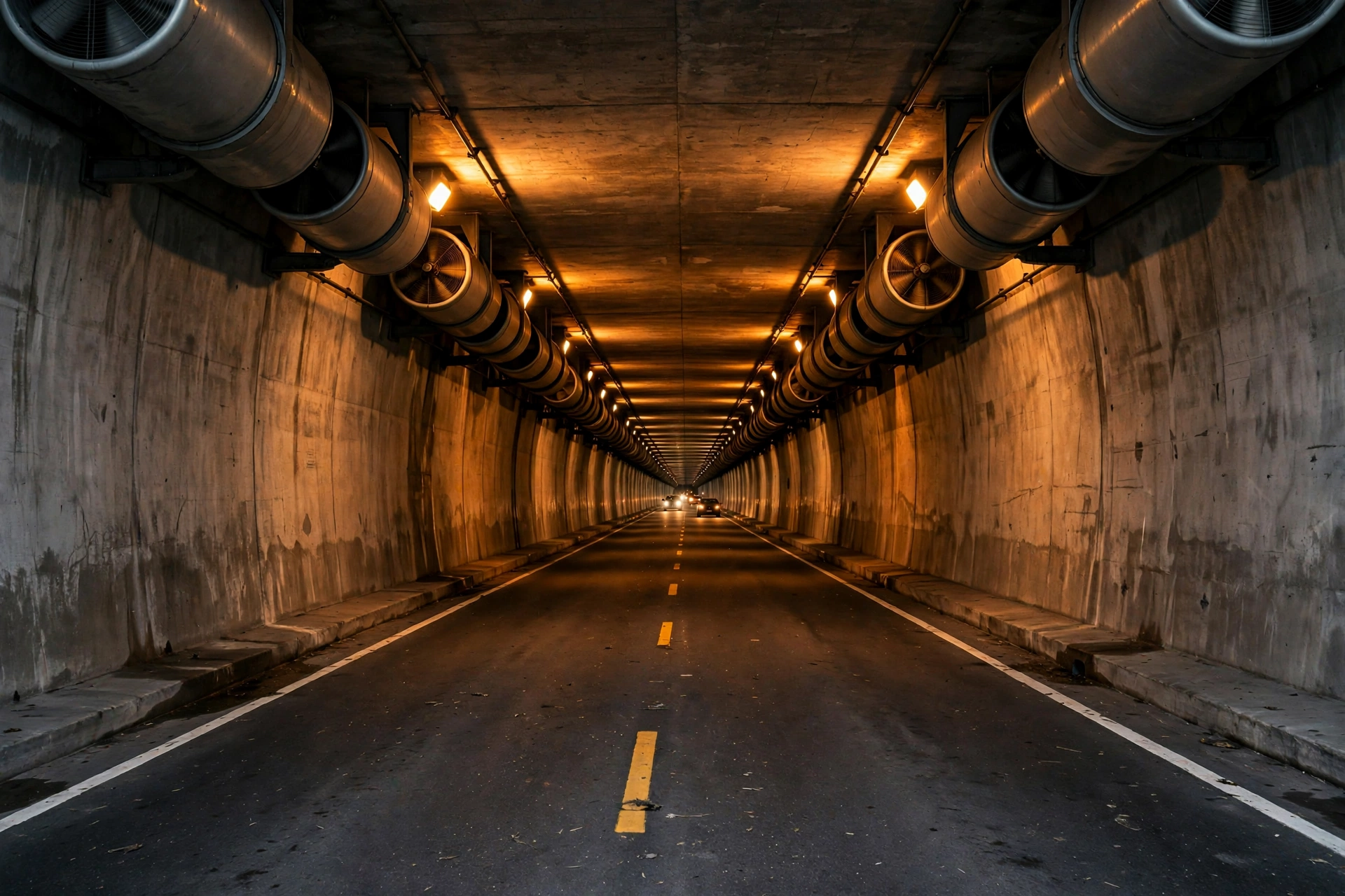
The jet fan is the defining load of a road tunnel. A typical two-lane bore carries between 8 and 24 jet fans, mounted in pairs on the ceiling, each one a cylindrical axial fan 710–1,250 mm in diameter with a motor of 15–75 kW. In normal operation they run at low speed, or not at all, diluting exhaust fumes and keeping carbon monoxide below the tunnel’s air-quality limits. In a fire they run at full speed in one direction, pushing smoke toward one portal so that the other side of the fire stays clear enough for people to walk out. That single function — longitudinal ventilation, driving the air at or above the critical velocity — is what the whole emergency power system is built around.
A jet fan’s running load is modest. Its starting load is not. A 37 kW fan motor started direct-on-line draws 6–7 times its running current for the first second, which is roughly 220 kVA of starting demand for a machine that runs on 46 kVA. Put eight of those fans on one bus and ask them to start together, and the generator sees a wall of starting kVA it cannot climb. The fans are therefore started in groups, two or three at a time, with 10–15 seconds between groups, and the generator is sized on the largest group plus the running load of the fans already turning. A tunnel that sizes its set on the sum of the fan nameplates buys a machine twice as large as it needs. A tunnel that sizes on running load alone buys a machine that trips the first time the fans start.
The fans also have to survive the fire they are fighting. A jet fan specified for emergency duty is rated to keep running in hot smoke — commonly 250°C for one hour or 300°C for two hours under EN 12101-3, with some national rules demanding 400°C for two hours. The rating matters because a fan that stops when the smoke reaches it is worse than no fan at all: the ventilation design assumed it would run. The generator that feeds it has to be just as durable in its own way. It sits in a portal building or a surface compound, outside the smoke, but its cooling air, its fuel and its control wiring all have to keep working while the tunnel fills with smoke and the fire service floods the roadway with water.
Emergency lighting and the way out
Emergency lighting is the smallest load in the tunnel and the one with the least tolerance for a gap. The lighting along the escape route — the low wall lights, the cross-passage signs, the illuminated arrows above the emergency exits — draws 5–15 kW in a typical bore, less than one jet fan. But the lights are the only thing between a driver and a dark concrete tube full of smoke, and they have to come up the instant the grid fails. European tunnel rules work to a minimum of 1 lux along the escape route, and the lights sit on a UPS-backed circuit so there is no dark second at all. The generator’s job is to take over from the UPS before the battery runs out, and then to keep the lights on for the rest of the outage.
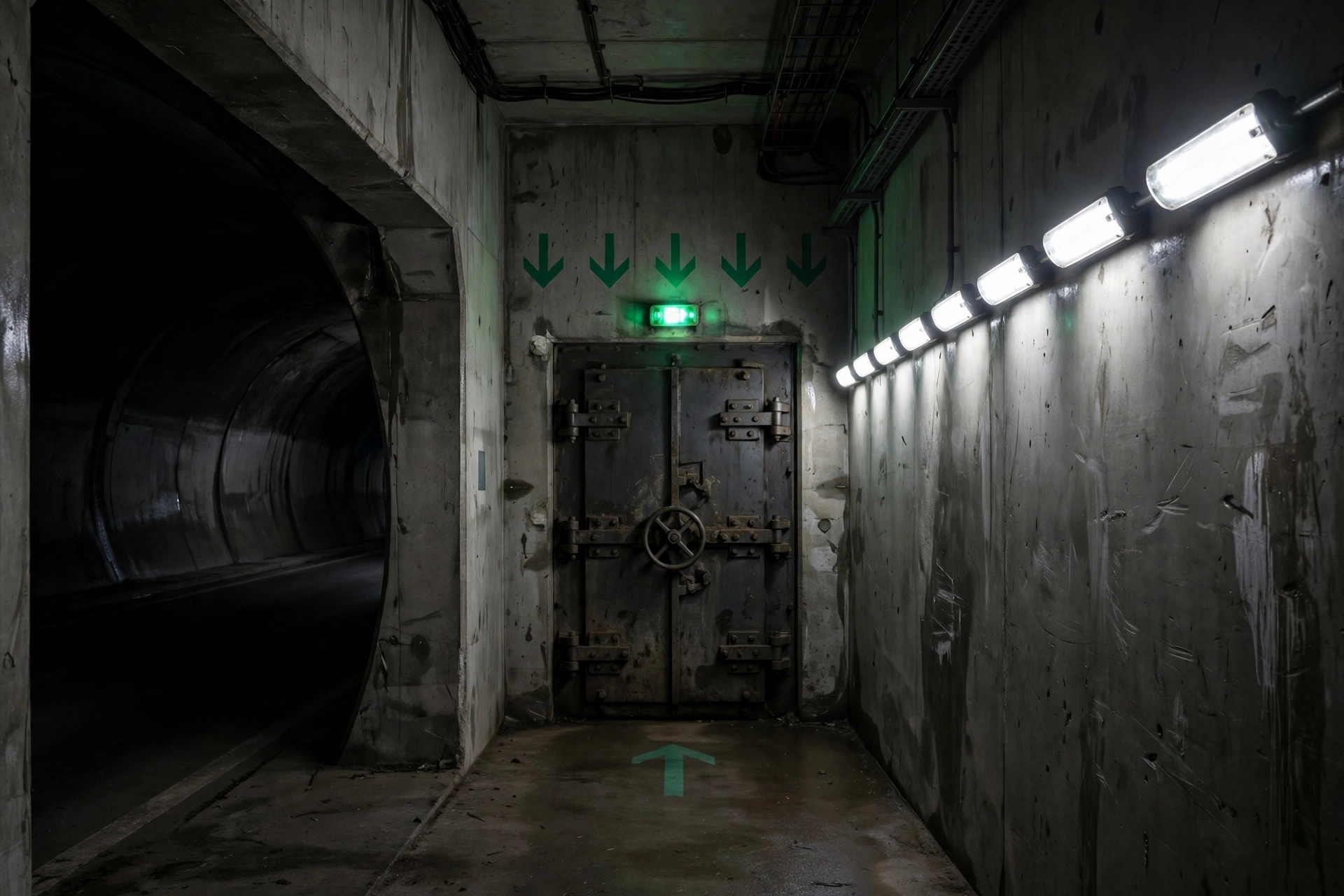
The escape route itself is part of the electrical design. In a twin-bore tunnel, cross-passages connect the two bores every 500 m at most under EU Directive 2004/54/EC, so that a driver who leaves a burning bore walks into a clean one. In a single-bore tunnel, the escape route is a protected walkway or a parallel safety gallery with its own lighting, its own ventilation and its own fire door every 500 m. Each cross-passage has a fire door, a sign, a light and a telephone or intercom, and each of those is on the generator’s essential bus. A tunnel that puts the cross-passage lights on a non-essential circuit has built an escape route that goes dark in the first minute of the fire it was built for.
Fire pumps, suppression and drainage
The fire-fighting load in a tunnel is a pump load, and pump loads start hard. A tunnel with a fixed water-based suppression system — deluge or water mist — carries one or two electric fire pumps of 55–110 kW each, plus a jockey pump of 5–10 kW that holds the system pressure between tests. A deluge pump started direct-on-line presents the same 6x starting surge as a jet fan, and it has to start while the fans are already running. The generator’s starting-kVA calculation has to include it, in the order the tunnel’s fire plan actually calls for it.
Drainage is the load that gets forgotten until the first flood. A tunnel is a low point by definition, and its sump pumps run whenever water collects — from fire-fighting, from a burst main, from groundwater seepage, from a storm that overwhelms the portal drainage. A typical sump pump draws 7.5–22 kW and starts frequently, which is exactly the kind of repeated motor-starting duty that punishes an undersized generator. A tunnel whose pumps lose power fills with water from the bottom up, and a tunnel with a metre of water on the roadway cannot be evacuated by walking.
Traffic control, SCADA and communications
The control room is the smallest load in the tunnel and the one that decides whether the outage is managed or merely endured. The SCADA system, the CCTV cameras, the variable message signs at the portals, the radio re-broadcast system that lets drivers hear the control room inside the bore, the emergency telephones and the fire alarm panel together draw 10–30 kW — less than a single large jet fan. But a control room that loses its screens loses the tunnel: it cannot see where the fire is, it cannot tell the fans which direction to push, and it cannot tell the drivers in the bore what to do. These loads sit on a UPS, and the UPS battery carries them for 15–30 minutes while the generator starts.
The radio re-broadcast system deserves a line of its own. A driver inside a tunnel cannot hear the police, the fire service or the tunnel operator unless the tunnel re-broadcasts their signals through a leaky feeder cable running the length of the bore. That cable and its amplifiers are on the essential bus, and they are the only way the control room can talk to the people it is trying to evacuate. A tunnel that loses its radio re-broadcast in a power cut has a thousand drivers in the dark with no instructions and no way to receive any.
Sizing the Set: Four Tunnel Types, Four Answers
Tunnel sizing does not work from length alone. A 400 m underpass under a city street and a 400 m mountain tunnel carry different loads, because the mountain tunnel has jet fans and the underpass may have none. The four bands below are the starting point most tunnel engineers work from, and the numbers are essential load — the load that must run when the grid is gone — not the tunnel’s total connected load. The fans, the lighting, the pumps and the control room decide the set. Everything else is shed.
| Tunnel type | Length | Typical essential load | Typical set |
|---|---|---|---|
| Short urban underpass | Under 300 m | 80–200 kW | 100–250 kVA |
| Medium two-lane tunnel | 300 m–1.5 km | 200–600 kW | 250–750 kVA |
| Long twin-bore tunnel, per bore | 1.5–5 km | 600–1,600 kW | 750–2,000 kVA |
| Immersed tube / very long tunnel | Over 5 km | 1,600 kW and up | 2,000 kVA+ or multiple sets |
The table is a guide, not a specification. Two tunnels of the same length can need sets a full size apart, because the number of jet fans, the fire-pump size and the ventilation mode are what drive the number. The worked method is the generator sizing guide approach — list every essential load, count the starting kVA of the largest motor group, add the running kVA of everything already on, and then check the result against the generator’s voltage dip and frequency dip limits. A set that passes on kVA and fails on voltage dip will still stall the fans.
Short urban underpass: 100–250 kVA
A short underpass — a road dipping under a railway or a city square for 100–300 m — often has no mechanical ventilation at all. Natural ventilation and the piston effect of the traffic carry the fumes out, and the essential load is lighting, drainage, the control room and the signals at the portals. A 100–250 kVA set covers it, and the most common mistake is buying a 500 kVA set “for safety” and then running it at 20–30% load for its whole life. A diesel engine that never gets properly loaded glazes its cylinder bores, builds up unburned fuel in the exhaust — wet stacking — and fails its monthly test. The right set for an underpass is the small one, loaded properly, not the large one bought for comfort.
Medium two-lane tunnel: 250–750 kVA
A medium tunnel — 300 m to 1.5 km, a single bore with two lanes — is where the jet fans arrive and the sizing gets serious. Eight to sixteen fans of 22–37 kW each, a fire pump of 55–75 kW, emergency lighting, drainage and the control room add up to 200–600 kW of essential load, and the starting kVA of the largest fan group decides the set. A 250–750 kVA machine covers the band, with the upper end reserved for tunnels with large fans, a deluge system and a steep gradient — a tunnel on a gradient needs more ventilation than a flat one, because the chimney effect fights the fans in one direction and helps them in the other.
Long twin-bore tunnel: 750–2,000 kVA per bore
A long twin-bore tunnel — 1.5–5 km, one bore per direction — is two tunnels that share a control room. Each bore gets its own generator, because a single set feeding both bores is a single point of failure for a structure that has two independent escape routes. A bore in this band carries 16–24 jet fans, a 75–110 kW fire pump, cross-passage lighting and ventilation for every cross-passage, and a control room share, which puts the essential load at 600–1,600 kW and the set at 750–2,000 kVA. The two sets are usually identical, so that one set of spares covers both, and each set is sized to carry its own bore plus the cross-passages that lead into it.
Immersed tube and very long tunnels: multiple sets
Above 5 km, and for immersed-tube tunnels under a river or a harbour, the answer stops being one set and becomes a system. The Lærdal Tunnel in Norway — 24.5 km, the longest road tunnel in the world — is divided into ventilation sections, each with its own fans, its own power supply and its own emergency power. A tunnel of this scale carries two or three sets of 1,000–2,000 kVA, sometimes with a medium-voltage distribution system at 11 kV feeding ventilation stations along the bore, because a low-voltage cable run of 5 km loses too much voltage to be useful. The sets are paralleled or split by section, and the design question is no longer “how big” but “how many, and where” — a question that belongs to the tunnel’s electrical consultant, not to a generator catalogue.
The rating question: standby, and the ten seconds
Tunnel generators are specified on the standby rating, and the reason is the same one that governs every life-safety installation. A tunnel set runs for a few hundred hours a year at most — weekly tests, monthly loaded runs and the occasional real outage — so the standby and prime ratings distinction matters in one direction only: the standby rating is the number the set can carry for the duration of an emergency, and the prime rating is the number it can carry indefinitely. A tunnel that buys on the prime rating and then asks the set to carry a standby load during a 48-hour outage is asking for a machine that was never rated for the job. The specification should state the standby rating, the NFPA 110 Level 1 classification, Type 10 — power restored within 10 seconds — and the Class, which is the fuel autonomy in hours. A Class 48 set carries its load for 48 hours on its own fuel. A Class 24 set carries it for 24 hours. The class is a contract term, not a guess.
Ventilation: The Load That Decides Everything
Ventilation is the load that decides the generator, and it is also the load that decides whether anyone survives a fire. In a tunnel fire, the danger is not the flame. It is the smoke — hot, toxic, and fast. A heavy goods vehicle fire reaches 20–30 MW within minutes, and the smoke it produces fills a tunnel bore faster than people can walk out of it. The ventilation system’s job is to push that smoke in one direction, away from the people, and to keep the air on the escape side moving fast enough that the smoke cannot roll back over their heads. That speed is the critical velocity, and the generator’s job is to keep the fans turning at the speed that produces it.
Critical velocity and the smoke that comes back
Critical velocity is the air speed at which smoke stops flowing back against the ventilation direction — the phenomenon called backlayering. For a 30 MW design fire, the figure most tunnel codes work to, the critical velocity is roughly 2.5–3 m/s, depending on the tunnel’s gradient and cross-section. Below that speed, smoke rolls back along the ceiling toward the people who are trying to escape. Above it, the smoke is pushed downstream, and the upstream side stays clear. The difference between 2 m/s and 3 m/s in a tunnel is the difference between an evacuation and a trap, and the fans have to reach that speed while the fire is already burning and the tunnel is already full of smoke.
The design fire is the number that sets the scale. PIARC, the World Road Association, works to a 30 MW design fire for a heavy goods vehicle, and some national rules use 50 MW or even 100 MW for tunnels carrying dangerous goods. A 30 MW fire is a lorry and its load burning freely. A 50 MW fire is a fuel tanker. The generator does not care which one the tunnel was designed for, except in one respect: the bigger the design fire, the higher the critical velocity, the more fans, and the bigger the set. A tunnel that upgrades its design fire from 30 MW to 50 MW without upgrading its generator has bought ventilation it cannot power.
Jet-fan starting surge: the 6x problem
The jet fan is a motor-starting problem in its purest form, and it is worth understanding in numbers, because the numbers are what the generator sees.
| Fan diameter | Motor | Thrust | Running kVA | Starting kVA (DOL) |
|---|---|---|---|---|
| 710 mm | 15 kW | ~350 N | ~19 kVA | ~110 kVA |
| 900 mm | 22–30 kW | ~500–700 N | ~28–38 kVA | ~170–230 kVA |
| 1,000 mm | 30–37 kW | ~700–900 N | ~38–46 kVA | ~230–280 kVA |
| 1,250 mm | 45–75 kW | ~1,000–1,300 N | ~56–94 kVA | ~340–560 kVA |
A single 37 kW fan draws about 46 kVA running and roughly 280 kVA for the first second of a direct-on-line start. Six of them started together present 1,680 kVA of starting demand to a generator that only needs to carry 280 kVA once they are all turning. No tunnel starts its fans that way. The standard answer is staged starting: the fans are divided into groups of two or three, each group started 10–15 seconds after the last, so that the generator never sees more than one group’s starting surge on top of the running load of the groups already turning. The same motor starting discipline that governs a factory floor governs a tunnel bore, with one difference: in a tunnel, the starting sequence is a life-safety sequence, written into the fire plan, and it is tested under load, not assumed.
Variable-speed drives change the arithmetic. A fan on a VSD starts softly, drawing little more than its running current, and the generator can be smaller — sometimes a full size smaller. The trade is complexity: a VSD is an electronic device in a hot, smoky environment, and it needs its own cooling, its own protection and its own spares. Tunnels that use VSDs on their fans size the generator for the soft-start load and keep a direct-on-line bypass for the day the drive fails. Tunnels that do not use VSDs size the generator for the staged direct-on-line load and accept the larger set. Both answers work. Neither works if the sizing was done on running load alone.
The ten-second start and the staged fan sequence
The sequence that runs when the grid fails is the most rehearsed ten seconds in the tunnel’s life. The automatic transfer switch senses the loss of mains, signals the generator to start, and the set reaches rated speed and voltage within 10 seconds under NFPA 110 Type 10. The UPS has carried the lighting, the SCADA system and the radios through those ten seconds. Then the transfer switch closes, and the generator picks up the essential bus in a fixed order: lighting and control first, then the fans in their staged groups, then the fire pump if the fire plan calls for it. The whole sequence, from grid failure to all fans at full speed, takes 60–90 seconds in a typical tunnel.
Ninety seconds sounds slow, and it is the number that tunnel operators argue about most. The argument is settled by the physics of the fire: a vehicle fire takes 5–10 minutes to reach its peak heat release, and the smoke layer takes minutes, not seconds, to descend to head height. A ventilation system that is fully running within ninety seconds is running well before the smoke becomes unsurvivable. The ten-second figure that matters is the generator’s start time, because the lights and the radios cannot wait ninety seconds. The fans can, as long as they start in their groups and reach critical velocity before the smoke layer drops. A tunnel that tests its start sequence once a year and finds it takes four minutes has found a problem that needs fixing before the next fire, not after it.
Three Tunnels, Three Outages
Three fires in three years rewrote road tunnel safety in Europe, and each one taught a different lesson about emergency power. They are worth reading together, because the lesson of the first is about ventilation, the lesson of the second is about detection, and the lesson of the third is about what happens when both fail at once.
Mont Blanc, 24 March 1999: the ventilation that pushed the smoke the wrong way
The Mont Blanc Tunnel is 11.6 km long, a single bore with two lanes, running under the highest mountain in Western Europe between France and Italy. On the morning of 24 March 1999, a Belgian-registered Volvo FH12 tractor with a refrigerated trailer, carrying flour and margarine, entered from the French side. At about 10:49, smoke appeared from under the cab. The driver stopped 6 km from the French portal to investigate, and the fire took hold. Within 15 minutes it was out of control. 39 people died, 14 were injured, and the fire burned for 53 hours at temperatures estimated at 1,000°C — the margarine load alone was equivalent to a 23,000-litre oil tanker.
The ventilation system is what turned a truck fire into a catastrophe. The tunnel’s smoke extraction capacity was about half that of comparable tunnels built more recently, and the extraction fans were run from two separate control rooms, one French and one Italian, with no single command. Shortly after the fire broke out, an Italian operator reversed the fans, pumping fresh air in from the Italian side in the belief that it would help people breathe. It did the opposite: it fanned the flames and drove the toxic smoke — carbon monoxide and hydrogen cyanide — toward the French side, where the trapped vehicles were. The ventilation system drove the smoke back down the tunnel faster than anyone could run to safety, and the fumes disabled vehicle engines, including the fire engines, which had to be abandoned. The tunnel’s electrical system failed, the lights went out, and drivers who left their cars for the seventeen pressurised emergency bunkers stumbled in the dark and were overcome by fumes within minutes. Most of the dead were killed within 15 minutes of ignition.
The official report made 41 recommendations, and the central one was about ventilation capacity: the tunnel’s smoke extraction should be doubled, to remove 110 m³/s of smoke from any 600 m length of tunnel. The tunnel closed for three years, reopening on 9 March 2002 after a complete overhaul of its safety systems — a single command post, new ventilation, new escape routes, and a generator and emergency power system that no longer depended on two countries agreeing in the middle of a fire. The lesson for any tunnel operator is the one Mont Blanc paid for in lives: ventilation is a system, and a system with two commanders and half the required capacity is not a system at all.
Gotthard, 24 October 2001: the collision that became a fire
The Gotthard road tunnel in Switzerland is 16.9 km long, the third-longest road tunnel in the world at the time, carrying the main north–south route through the Alps. On 24 October 2001, two heavy goods vehicles collided head-on inside the tunnel, and the collision became a fire. 11 people died and more than 30 were injured. The tunnel closed for two months.
Gotthard’s lesson was different from Mont Blanc’s. The ventilation system worked as designed, and the tunnel’s emergency power held. The problem was detection and decision: the fire was not identified quickly enough, the traffic was not stopped quickly enough, and vehicles kept entering the tunnel after the fire had started. The tunnel’s operators learned that a ventilation system, however powerful, cannot save people who are still driving into a fire they cannot see. The response was faster automatic fire detection — systems that can locate a fire within 15 m under NFPA 502 — automatic tunnel closure, and a control room with the authority to stop traffic without waiting for a human decision. The generator’s role in that chain is to keep the detection, the signs and the barriers powered while the decision is made. A tunnel that detects a fire in thirty seconds and closes in sixty has a ventilation system that works on a tunnel full of people who were warned. A tunnel that detects it in five minutes has a ventilation system working on a tunnel full of people who were not.
Tauern, 29 May 1999: the paint truck and the pile-up
The Tauern Tunnel in Austria is 6.4 km long, carrying the main route south from Salzburg toward Italy. On 29 May 1999, a lorry carrying cans of paint collided with a car inside the tunnel. The paint caught fire, the fire spread to following vehicles, and a pile-up formed behind the blaze. 12 people died and about 50 were injured.
Tauern’s lesson was about the load the fire itself puts on the tunnel’s systems. A paint fire burns hot and fast, and the smoke it produces is thick, black and acrid — the worst kind for visibility and the worst kind for the fans. The tunnel’s ventilation could not clear the smoke fast enough for the drivers caught behind the pile-up, and the emergency lighting and the escape-route signs were the only guidance those drivers had. Tauern, like Mont Blanc, was a single-bore tunnel with two-way traffic, and the two-way layout is what made the pile-up possible: there was nowhere for the traffic behind the fire to go. The tunnel was later rebuilt as a twin-bore tunnel, one bore per direction, with a second tube opened in 2011. The generator lesson is the same one every tunnel teaches in the end: the emergency power system is sized for the worst fire the tunnel can credibly have, not the average one, and the worst fire is a heavy goods vehicle carrying something flammable, in a bore full of traffic, with the ventilation running against a gradient.
Fuel Autonomy: How Long the Tunnel Lasts
A tunnel generator that runs out of fuel during a fire is a ventilation system that stops in the middle of the evacuation. Fuel autonomy is therefore a safety figure, not a logistics figure, and it is set by the tunnel’s fire plan and its grid restoration time, not by the size of the tank that happened to fit in the portal building.
| Set size | Load at 75% prime | Fuel use | 24 hours | 48 hours | 72 hours |
|---|---|---|---|---|---|
| 250 kVA | ~140 kW | ~35 L/h | 840 L | 1,680 L | 2,520 L |
| 500 kVA | ~340 kW | ~70 L/h | 1,680 L | 3,360 L | 5,040 L |
| 1,000 kVA | ~680 kW | ~140 L/h | 3,360 L | 6,720 L | 10,080 L |
| 2,000 kVA | ~1,360 kW | ~280 L/h | 6,720 L | 13,440 L | 20,160 L |
The fuel figures are typical consumption at 75% of prime load. A Cummins C500D5 — 500 kVA standby, 455 kVA prime — burns 93.2 L/h at full prime load and 69.9 L/h at 75%, so the 500 kVA row above is a measured figure, not an estimate. The other rows scale from it, and the scaling holds because diesel consumption per kilowatt is roughly constant across the range: about 0.2 L per kWh. A tunnel that knows its load knows its fuel burn, and a tunnel that knows its fuel burn knows its autonomy to the litre.
24, 48 or 72 hours — who decides
The autonomy figure is set by whoever owns the risk. NFPA 110’s Class system gives the language: Class 48 means the set carries its load for 48 hours on the fuel stored on site, Class 24 means 24 hours, Class 72 means 72 hours. Many European tunnel authorities specify 48 hours as the minimum for a major tunnel, on the reasoning that a grid fault that takes longer than two days to repair is a regional disaster, not a tunnel problem, and that a fuel tanker can reach any portal in two days. Tunnels in remote mountain areas, or tunnels whose only access road crosses the same terrain that caused the outage, are more often specified at 72 hours. Short urban tunnels, where the grid operator can restore supply in hours and a fuel tanker can reach the portal in minutes, are sometimes specified at 24 hours. The number is a judgement about the site, and it should be written into the specification as a Class, so that the tank size is a consequence of the decision, not an accident of the building.
The day tank, the bulk tank and the transfer pump
Fuel reaches the engine through two tanks, and the two-tank arrangement is itself a safety measure. The day tank sits next to the generator, holds 8 hours of fuel at full load, and feeds the engine by gravity. The bulk tank sits outside the generator room — often buried, or in a separate fire-rated compound — and holds the rest of the autonomy, feeding the day tank through a transfer pump with a float switch. The arrangement exists so that a fire in the generator room cannot reach the bulk of the fuel, and so that a leak in the bulk tank cannot drain into the generator room. The transfer pump is on the generator’s essential bus, because a generator that cannot refill its own day tank runs for eight hours and then stops, whatever the bulk tank holds.
The slow failure that catches tunnels is diesel fuel ageing, because a tunnel generator may run for only 50–100 hours a year. Fuel that sits in a bulk tank for two years absorbs water, grows microbes and loses its cetane, and a generator that starts on degraded fuel may start, run for ten minutes, and then stop on a clogged filter — in the middle of the outage it was bought for. The answer is the same discipline that governs any standby set: test the fuel every 6 months, polish it or replace it when the water content or the microbial count rises, and keep the tank full so that condensation has nowhere to form. A tunnel that tests its fuel twice a year and changes it when the test says so has a generator that will run for its full autonomy. A tunnel that does not has a generator that will run until the filter clogs.
Refuelling a tunnel that is closed
The last fuel question is the one nobody asks until the outage lasts longer than the autonomy. A tunnel that is closed to traffic is also closed to the fuel tanker, unless the refuelling route was planned in advance. The bulk tank’s fill point should be outside the tunnel, accessible from the surface road, with a connection the tanker can reach without entering the bore. The fill point should be signposted, the tanker driver should know the route, and the tunnel’s emergency plan should name the fuel supplier and the number to call. A tunnel with 48 hours of fuel and a refuelling plan that takes 24 hours to execute has, in practice, an autonomy of 72 hours. A tunnel with 48 hours of fuel and no plan has an autonomy of 48 hours, and a problem on the 49th.
Where the Generator Sits: Exhaust, Heat and the Portal Building
A tunnel generator lives in one of two places: inside the portal building at the tunnel mouth, or in a surface compound a short distance from the portal. The choice is made by the site, and both answers have a failure mode that has to be designed out.
Portal building or surface compound
The portal building is the obvious home. It is already there, it already has power, drainage and a road, and the cable run from the generator to the tunnel’s essential switchboard is short — often under 50 m. The risk is that the portal building is also where the smoke goes. In a fire, the ventilation system pushes smoke toward one portal, and if the generator’s cooling-air intake is on that side, the set breathes smoke. A diesel engine that breathes smoke loses power, and an engine that loses power while the fans are running at full load trips on overload. The answer is to take the cooling air from the clean side of the building, or from above the smoke layer, and to fit the intake with a fire damper that closes if the smoke reaches it. A generator room that can be starved of air by its own tunnel’s ventilation system is a design error, not a bad luck story.
The surface compound avoids the smoke problem and creates a different one: distance. A generator 200 m from the portal needs a cable run that loses voltage, needs its own access road for the fuel tanker and the service engineer, and needs its own security — a compound in a remote mountain valley is an easy target for theft and vandalism. The cable run is the engineering question: at 400 V, a 200 m run carrying 1,000 kVA needs a cable cross-section that costs more than the generator room it replaced, which is why large tunnel sets are sometimes specified at 11 kV with a step-down transformer at the portal. The compound is the right answer when the portal has no room, or when the portal building is itself at risk from rockfall or flooding. It is the wrong answer when it is chosen because nobody wanted to argue about the space.
Exhaust, emissions and the neighbours
A tunnel generator’s exhaust is a planning issue before it is an engineering one. The set sits at the portal, the portal sits in a valley or at the edge of a town, and the exhaust stack discharges diesel fumes where people live, walk and drive. The stack height is set by the local air-quality rules, and in a valley it is set by the valley: a stack that discharges into still air at the bottom of a valley will be read as smoke by every driver entering the tunnel. The usual answer is a stack that rises above the portal roofline, with a silencer that keeps the set’s noise below the local limit — typically 70–75 dB(A) at 7 m for a silent canopy set, and lower where housing is close.
Emissions are the second neighbour problem. A tunnel generator is a standby set, and in most jurisdictions a standby set is exempt from the strictest emission limits — but only while it is genuinely on standby. A tunnel that runs its set for a weekly test at full load for four hours is not running a standby set, and the local authority may not see it that way. The specification should state the emission standard — EU Stage V, US EPA Tier 4 Final, or the local equivalent — and the test regime should be short enough and loaded enough to keep the set healthy without turning the portal into a source of complaint. The weekly test, the monthly loaded run and the 36-month four-hour test belong in the tunnel’s maintenance schedule, not in the operator’s memory. A 1,000 kVA set running at 30% load for an hour a week burns about 40 litres of fuel and produces a plume of blue smoke that the whole valley can see. A set tested at 70% load for thirty minutes burns less, smokes less, and tells the operator more about the state of the machine.
Flood, drainage and the low point
A tunnel is a low point, and its portal is where the water collects. A generator room at portal level, or below it, is a generator room that floods — from a storm, from a burst water main, from the fire-fighting water that runs downhill out of the bore. The set should sit above the 1-in-100-year flood level for the site, on a plinth that keeps the engine, the alternator and the control panel dry when the portal road is under 300 mm of water. The fuel tank should sit higher still, or be bunded so that a flood cannot float it off its plinth or carry its contents into the drainage system. A tunnel that floods its generator room in the same storm that takes out the grid has lost both of its power supplies to the same water, and the lesson is the one every tunnel engineer already knows: the generator room is the last room in the tunnel that should be allowed to get wet.
Frequently Asked Questions
What size generator does a road tunnel need?
A short urban underpass typically needs a 100–250 kVA set, a medium two-lane tunnel needs 250–750 kVA, and a long twin-bore tunnel needs 750–2,000 kVA per bore. The jet fans decide the size, and the set is sized on the starting kVA of the largest fan group plus the running load of everything else, not on the sum of the nameplates.
Do road tunnels need a backup generator?
Yes, in practice every tunnel longer than 300 m needs one. NFPA 502 requires an on-site generator as a secondary power source for the systems that keep a tunnel survivable — ventilation, emergency lighting, fire pumps and communications — and EU Directive 2004/54/EC requires emergency power for tunnels over 500 m on the trans-European network. A tunnel without a generator has no ventilation, no lighting and no way out when the grid fails.
How long can a road tunnel run on a generator?
As long as the fuel lasts. A tunnel specified to NFPA 110 Class 48 runs for 48 hours on its stored fuel, and Class 72 runs for 72 hours. A 1,000 kVA set at 75% load burns about 140 L/h, so 48 hours needs roughly 6,700 litres and 72 hours needs roughly 10,100 litres. Refuelling during the outage extends the autonomy, if the fill point is reachable from the surface road.
What happens to a road tunnel during a power outage?
The tunnel closes to traffic, the signals go red at both portals, and the generator starts within 10 seconds. The emergency lighting comes up on UPS, the fans start in staged groups and reach critical velocity within 60–90 seconds, and the control room keeps its screens, its radios and its cameras. The vehicles already inside drive out or wait; nobody new enters until the grid returns or the fire service clears the bore.
Can a diesel generator power a tunnel ventilation system?
Yes, and it is the standard answer. A diesel set powers the jet fans, the smoke extraction fans and the control system that runs them, with the fans started in groups of two or three so that the starting surge stays within the generator’s capacity. A 37 kW jet fan needs about 280 kVA to start and 46 kVA to run, so the generator is sized on the starting sequence, not on the running load. Variable-speed drives reduce the starting surge further, at the cost of added electronics in a hot, smoky environment.
Specification Checklist
- Size the set on the starting kVA of the largest fan group plus the running load of everything already on, and check the voltage dip against the fan motors’ tolerance.
- Rate the set on standby, to NFPA 110 Level 1, Type 10, with the Class — 24, 48 or 72 hours — written into the specification as a contract term.
- Specify reversible jet fans rated for 300°C for two hours under EN 12101-3, and confirm the rating in the fan’s test certificate, not in the brochure.
- Stage the fan start in groups of two or three with 10–15 seconds between groups, and write the sequence into the fire plan so it is tested, not assumed.
- Put the emergency lighting, the PA, the radio re-broadcast system and the SCADA on a UPS-backed essential bus, and size the UPS battery for 30 minutes at full load.
- Size the day tank for 8 hours at full load and the bulk tank for the full autonomy, with the transfer pump on the essential bus and the fill point reachable from the surface road.
- Keep the set above the 1-in-100-year flood level, take its cooling air from the clean side of the portal building, and fit a fire damper on the intake.
- Choose a silent canopy and a stack above the portal roofline where housing is close, and specify the emission standard — EU Stage V or the local equivalent — in the order.
- Test the set monthly at 30% load or more for 30 minutes, run the full 4-hour Level 1 test every 36 months, and test the fuel every 6 months.
- Fit remote monitoring with fuel-level, fan-status and start-failure alarms, so that a set that fails its weekly test is known about the same day, not at the next fire.
A tunnel generator is bought once and relied on for thirty years, and the tunnels that get it right are the ones that treat it as a life-safety system, not as a piece of electrical equipment. The fans, the lights, the pumps and the radios all depend on it, and the people inside the bore depend on all of them. If the tunnel is on the drawing board now, the time to size the set, place the room and write the start sequence is now — before the concrete is poured and the choices become expensive. To discuss a set for a tunnel project, including the sizing, the ventilation sequence and the fuel autonomy, contact PAVO.