

What Size Generator Does a Gas Processing Plant Need? | PAVO
A gas processing plant does not stop like a factory. It stops like a pressure vessel with nowhere to send its gas — and the flare is the only thing left standing between the plant and the sky.
What size generator does a gas processing plant need? A 50 MMscfd plant needs a 250–500 kVA set for its essential loads, a 250 MMscfd cryogenic plant needs 1,000–2,500 kVA, and the full process load runs into tens of megawatts that no diesel set can carry. The generator protects the control, safety and restart loads, not the whole plant.
- What a Gas Processing Plant Actually Needs Power For
- Sizing Bands by Plant Throughput
- The Flare-and-Vent Window: What an Outage Really Costs
- Compression: The Load That Decides the Set
- Hazardous Areas: Where the Generator Can and Cannot Go
- Fuel Autonomy: How Long a Plant Can Really Run
- Frequently Asked Questions
- Specification Checklist
What a Gas Processing Plant Actually Needs Power For
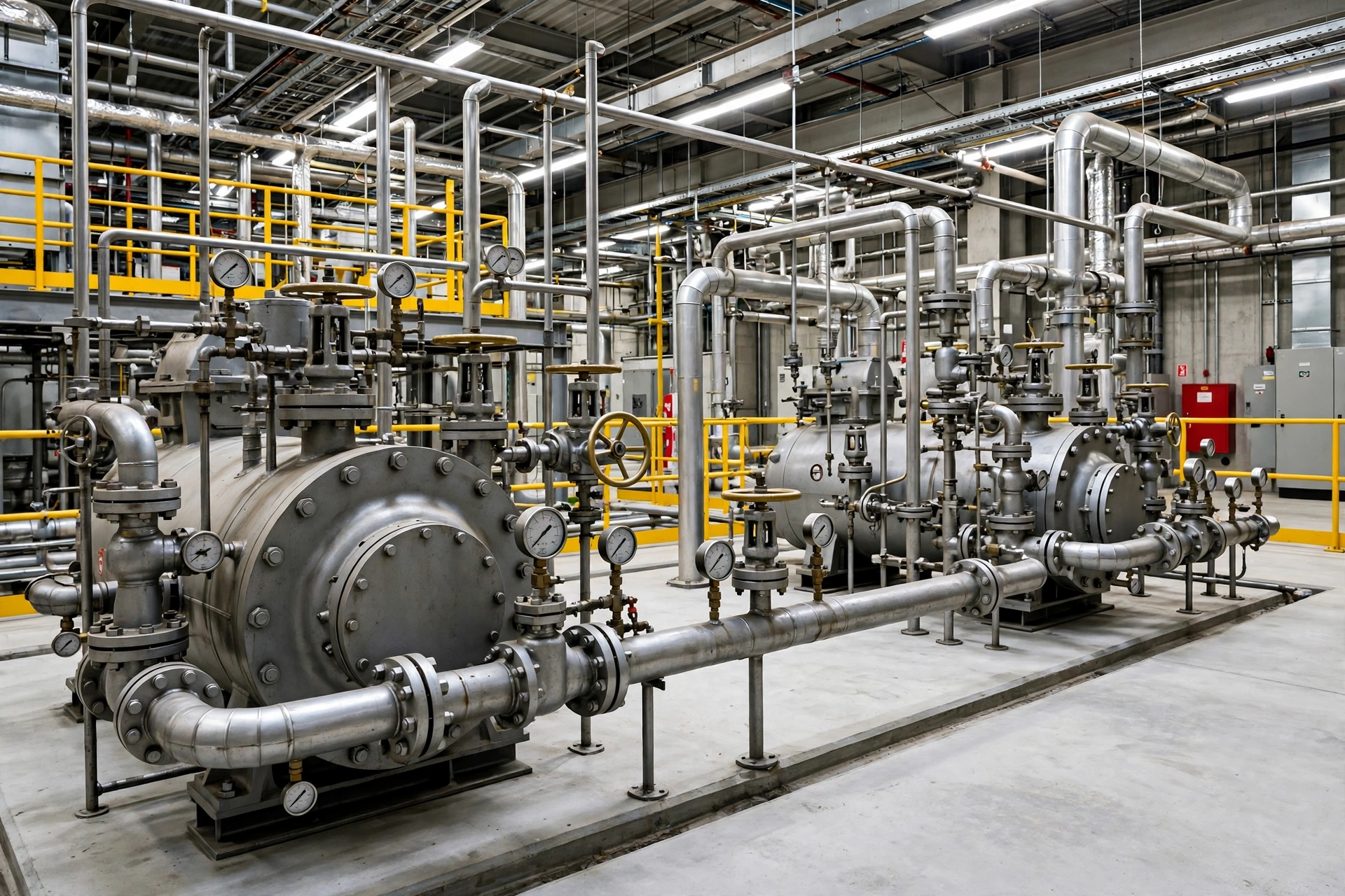
Raw gas arrives at a processing plant wet, sour and under pressure. It leaves as pipeline sales gas and as natural gas liquids — ethane, propane, butane and natural gasoline. Between those two points the plant strips out water, hydrogen sulphide and carbon dioxide, chills the stream until the liquids drop out, compresses the sales gas back up to pipeline pressure, and stores the liquids for truck or pipeline shipment. Every one of those steps needs power, and the power is not evenly spread. Compression takes the most. Heat takes the next most. Everything else — controls, lighting, pumps, air — is small by comparison, and it is the small part that the generator is bought to protect.
The split matters because buyers size the wrong thing. A plant that draws 20 MW in normal operation does not need a 20 MW generator. It needs a generator that keeps the instruments alive, the safety systems armed, the flare lit, the critical pumps turning and the compressors restartable. That slice is typically 5–15% of the plant’s total electric load. The rest — the big compressors, the refrigeration trains, the reboilers — stops with the grid, and the plant is designed for that. The question is never whether the generator can run the plant. It is whether the generator can hold the plant in a safe state until the grid returns, and whether it can bring the plant back without a week of damage.
The loads fall into three tiers, and the tiers decide the specification. The first tier is the process that cannot stop: dehydration and sweetening, where a temperature or pressure excursion ruins the solvent or the product. The second tier is the rotating equipment: compressors and refrigeration, where the starting surge decides the set size. The third tier is the utilities and safety systems: instrument air, cooling water, fire water, flare pilots, control room and communications. A set that covers the third tier keeps the plant safe. A set that covers the first two as well shortens the restart from days to hours. The budget has to state which one it is buying, because the difference between them is roughly ten times the kVA figure.
Dehydration and Sweetening
The first thing raw gas meets is the inlet separator, then the amine contactor. The amine unit strips hydrogen sulphide down to pipeline specification — typically below 4 ppmv — and carbon dioxide to below 2%. The rich amine is regenerated in a stripper column, and the reboiler is the single largest heat user in the whole plant. In a published simulation of a gas sweetening and dehydration unit, the amine reboiler drew 45.63 kW of heat in a small unit, and the TEG dehydration furnace drew 100.7 kW — and that was a study-scale unit, not a commercial train. In a commercial plant the reboiler duty runs into megawatts of heat, usually supplied by gas-fired heaters rather than electricity, which is why the amine unit’s electric load is modest: circulation pumps, lean amine pumps, air coolers and fans, typically 100–400 kW for a 100 MMscfd train.
The electric load is small. The consequence of losing it is not. If the amine circulation stops, the contactor floods or dries out, untreated gas passes downstream, and the plant has to shut in the feed or flare it. If the TEG dehydration unit stops, wet gas reaches the cryogenic section, water freezes in the cold box, and the plant faces a thaw and a re-dry that takes a day. The dehydration unit is the reason the generator’s essential bus includes the amine and glycol pumps: they are small loads with a large blast radius. A 250 kVA set carries them without noticing. A plant with no generator on them loses a day of production to a ten-second outage.
Compression and Refrigeration
Compression is the load that decides everything else. A gas plant compresses at the inlet, compresses between process stages, and compresses the sales gas back up to pipeline pressure — typically 800–1,200 psig — for export. The GPSA rule of thumb puts the shaft power at 30–40 HP per MMscfd for a compression ratio of 2.0, 55–70 HP per MMscfd at a ratio of 3.0, and 80–100 HP per MMscfd at a ratio of 4.0. A 100 MMscfd plant at a ratio of 3.0 needs 5,500–7,000 HP of shaft power for one compression stage — 4.1–5.2 MW — before the driver margin. The main sales-gas compressors are usually gas-turbine or gas-engine driven, not electric, precisely because the power is so large. The electric compressors are the smaller ones: inlet boosters, refrigeration compressors, instrument-air compressors and vapour recovery units.
The refrigeration train is the second large electric load. A cryogenic plant chills the gas to −100°C or colder in a turbo-expander, and the propane refrigeration loop that pre-cools the stream draws hundreds of kilowatts to several megawatts depending on the train size. The refrigeration compressors are large electric motors, and they start hard: a 2,500 HP motor draws five to seven times its running current for a second. The generator sizing guide sets out the step-by-step load-list method; the gas plant adds one rule to it, which is that the refrigeration compressors restart together when power returns, and the set has to survive that simultaneous restart or the plant trips again the moment it tries to come back.
Fractionation, Storage and Utilities
The liquids that drop out of the gas stream go to the fractionation train — de-ethaniser, de-propaniser, de-butaniser — where they are separated into ethane, propane, butane and natural gasoline. The fractionators are heated by reboilers and cooled by air coolers and cooling water, and their electric load is the pumps: reflux pumps, product pumps, condensate pumps, typically 200–600 kW for a 100 MMscfd plant. The storage side is quieter: sphere and bullet pumps, loading pumps, vapour recovery, metering and the tank farm, another 100–300 kW.
The utilities are the load the generator is actually bought for. Instrument air compressors and dryers, cooling-water pumps, fire-water pumps, the flare knock-out drum pumps, the control room, the DCS and SIS, the gas detection system, the communications and the emergency lighting. A 100 MMscfd plant’s utility and safety load runs 300–800 kW. It is the smallest number on the page and the most important, because it is the load that keeps the plant safe when everything else has stopped. The standby and prime ratings article explains why the rating on the nameplate matters here: a set that runs for 72 hours on a long outage is running on its prime rating, not its standby rating, and the difference is 10% of the kVA figure.
| Process unit | Typical electric load, 100 MMscfd plant | What happens if it stops |
|---|---|---|
| Inlet compression / boosting | 1,000–2,500 kW | Feed backs up into the gathering system |
| Amine sweetening (pumps, fans) | 100–400 kW | Untreated gas passes downstream |
| TEG dehydration (pumps, fans) | 50–200 kW | Wet gas reaches the cold box, water freezes |
| Refrigeration compressors | 500–2,000 kW | Liquids recovery stops, ethane lost to sales gas |
| Sales-gas compression (electric) | 2,000–5,000 kW | No export, pipeline pressure falls |
| Fractionation pumps | 200–600 kW | Liquids back up, columns flood |
| Utilities and safety systems | 300–800 kW | Instruments, air, fire water and flare pilots lost |
The table is the reason the specification starts with a load list, not with a kVA figure. Two plants processing the same 100 MMscfd can need sets that differ by a factor of three, because one of them has electric sales-gas compression and the other drives its compressors with gas turbines. The load list is measured at the distribution board, train by train, with the starting current of every large motor recorded. No load list, no quotation.
Sizing Bands by Plant Throughput
Sizing a gas plant generator starts with the throughput, because the throughput decides the compression, and the compression decides the load. A small gathering plant and a large cryogenic plant are not the same specification with a different number on the front. They are different plants, with different drivers, different starting surges and different fuel bills. The table below is the starting point — every plant has to be measured at its own switchboard, because the load depends on the drivers, not on the throughput alone.
| Plant size | Essential load | Recommended sets | Typical cost installed |
|---|---|---|---|
| Gathering plant, 10–50 MMscfd | 150–400 kW | 250–500 kVA, one set | $40,000–$120,000 |
| Mid-size plant, 50–100 MMscfd | 400–1,000 kW | 500–1,250 kVA, one set | $120,000–$280,000 |
| Cryogenic plant, 100–250 MMscfd | 1,000–2,500 kW | 1,250–3,125 kVA, 1–2 sets | $280,000–$650,000 |
| Large plant, 250–500 MMscfd | 2,500–5,000 kW | 3,125–6,250 kVA, 2–3 sets | $650,000–$1,500,000 |
The table assumes the set covers the essential bus — controls, safety systems, utilities, amine and glycol pumps, and the staged restart of one refrigeration compressor. It does not assume the set runs the sales-gas compressors. A plant that wants its main compressors on generator power is not buying a generator. It is buying a power station, and the answer is gas turbines, not diesel.
A 50 MMscfd Gathering Plant: 250–500 kVA
A gathering plant — 10–50 MMscfd, inlet separation, amine sweetening, TEG dehydration, one or two booster compressors and a sales-gas compressor — typically needs a single 250–500 kVA set. The worked example shows where the kVA goes. Amine and glycol pumps 80 kW. Instrument air and cooling water 60 kW. Control room, DCS, gas detection and communications 30 kW. Fire-water pump 75 kW on standby. Lighting and small loads 20 kW. The running load is 265 kW, or about 330 kVA at a power factor of 0.8.
The running load is not the set size. The booster compressor motor — a 200 kW motor starting direct-on-line — demands five to seven times its running current for a second, and the fire-water pump adds its own surge. What sizes the set is motor starting, not the running load. A 500 kVA set covers the gathering plant with room for the compressor restart, and it burns about 70 L/h at 75% load. A Cummins C500D5, rated 500 kVA standby and 455 kVA prime, covers most gathering plants, and it costs $70,000–$120,000 installed with a sub-base tank and an automatic transfer switch.
The mistake gathering plants make is buying the set for the running load and forgetting the restart. A plant that sizes for 330 kVA and buys a 350 kVA set will trip the first time the booster compressor restarts after an outage — and the outage is the one moment the compressor has to restart. The motor starting guide covers the locked-rotor kVA and the starting methods that cut it; the gas plant adds one rule, which is that the restart has to be sequenced, a few seconds apart, or the set sees the whole plant at once.
A 250 MMscfd Cryogenic Plant: 1,000–2,500 kVA
A cryogenic plant — 100–250 MMscfd, amine, dehydration, turbo-expander, propane refrigeration, fractionation and NGL storage — typically needs 1,000–2,500 kVA, as one or two sets. The essential load is 1,000–2,500 kW, and the sizing decision is not the total. It is the split: the refrigeration compressors are the load that cannot wait, and the fractionation pumps are the load that can. A 2,000 kVA set covers the controls, the utilities, the amine and glycol pumps and one refrigeration compressor on a staged restart, and the second compressor waits for the first to settle. The set costs $250,000–$450,000 installed, and it burns about 280 L/h at 75% load.
The cryogenic plant is also the size where the set is specified as two smaller sets rather than one large one, because a single set is a single point of failure for a plant that processes a quarter of a billion cubic feet a day. Two 1,250 kVA sets cost roughly 25% more than one 2,500 kVA set, and the plant buys them anyway, because a plant that loses its only generator during a storm loses its flare pilots, its instruments and its ability to restart safely. The automatic transfer switch staggers the compressor restarts across the two sets, a few seconds apart, so that the combined starting surge never hits either set at once — and the sequencing has to be designed, programmed and tested, because a set that is sized for the running load and never tested under a full restart will trip on its first real outage.
A 500 MMscfd Plant: The Honest Limit
A 500 MMscfd plant is where the honest limit has to be stated, because the numbers stop being generator numbers. Siemens supplied three residue compression trains for two 250 MMscfd cryogenic plants in the Delaware Basin, and each train is a 22,000 HP motor driving a multistage centrifugal compressor — 16.4 MW per train, 49 MW for the three. The traditional approach would have needed ten large reciprocating units; the centrifugal solution met the whole 500 MMscfd duty with three. No diesel generator set carries that. A 500 MMscfd plant’s full electric load runs 30–60 MW, and the generator covers the essential slice — 2,500–5,000 kW — which is roughly a tenth of the plant.
The Norwegian Kårstø plant makes the same point at a larger scale. Kårstø handles 88 million standard cubic metres of rich gas a day — about 3.1 billion cubic feet — and its sales-gas compressors are driven by three 12.32 MW gas turbines, with three electrically driven booster compressors behind them. The plant’s own power demand runs into tens of megawatts. A diesel set at Kårstø is not a production asset. It is a black-start and safety asset, and it is specified as one: it starts the plant’s own gas turbines, holds the control systems, and keeps the flare burning until the grid or the turbines take over.
The specification has to say this plainly, in writing, before the order is placed. A supplier that quotes a 3,750 kVA set — the largest in PAVO’s range — for a 500 MMscfd plant’s essential loads is quoting the right thing. A supplier that quotes the same set for the plant’s full load is quoting a fiction, and the plant will find out which one it bought on the first outage.
The Flare-and-Vent Window: What an Outage Really Costs
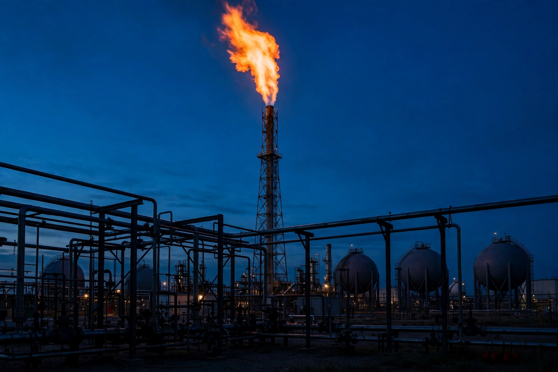
A gas plant measures an outage in cubic feet and in hours, not in kilowatt-hours. The grid fails, the automatic transfer switch moves the essential bus to the generator, and if everything works, the instruments never notice and the flare never lights. If anything in that chain fails, the plant starts venting and flaring within minutes, and it starts losing its production within hours. The arithmetic is worth doing before the outage, because it is the arithmetic that justifies the generator.
The window is the number that decides everything. A gas plant that loses power loses its compressors first, and the gas that was flowing through them has to go somewhere. The gathering system backs up, the wellhead pressure rises, the producers shut in their wells or flare at the wellhead, and the plant’s own vessels relieve to the flare header. A plant that processes 100 MMscfd and shuts down for 24 hours loses 100 million cubic feet of throughput, and at $3 per MMBtu that is roughly $300,000 of gas that was never processed — before the restart costs, the off-spec product, the flaring penalties and the damage to equipment that was never meant to stop hot.
Case 1: Winter Storm Uri and 38 Gas Plants
In February 2021, Winter Storm Uri cut power across Texas, and the gas system failed before the power system did. Cold weather disrupted 22 gas processing plants on Saturday 13 February, and ultimately 38 gas plants shut down or reduced production — equivalent to 8.9 billion cubic feet per day of lost gas processing capacity. Gas production in Texas fell 45%. Across the United States, gas output fell by about 21 billion cubic feet per day between 8 and 17 February, down 23% from almost 91 billion cubic feet per day immediately before the freeze, and Texas alone had more than 10 billion cubic feet per day offline.
The plants did not fail because their equipment froze. They failed because they lost power, and because many of them had not been registered as critical infrastructure, so the grid operator’s load shedding cut them along with the neighbourhoods. With no place to send the gas, producing wells vented or flared it — 1.6 billion cubic feet of methane in a single day. Gas prices on the Texas Gulf Coast traded above $160 per MMBtu, against $3 the week before. ERCOT shed as much as 27 GW of load, about 35% of forecast demand, and 69% of Texans lost power, with outages averaging 42 hours.
The Uri case is the one that gas plant managers quote, because it is the failure that looks like a weather problem and is actually a power problem. The plants that survived were the ones whose generators kept their instruments, their amine pumps and their flare pilots alive, so that the plant could shut down in an orderly way and restart when the grid returned. The plants that did not have that backup tripped hard, and the restart took days, because a cryogenic plant that stops cold has to be thawed, dried and re-cooled before it can take gas again. A 500 kVA set costs less than the gas a 100 MMscfd plant loses in a single day of outage.
Case 2: Joliet and Houston, September 2026
The second case is smaller and more recent, and it shows the same pattern at the scale of a single plant. At about 3:30 p.m. on 13 September 2026, a power outage led to a plant-wide shutdown at ExxonMobil’s Joliet refinery in Illinois. Power was restored around 7 p.m., and the refinery’s safety flare was activated during the upset. The company spent the next day assessing the site and investigating the cause. IIR Energy told Reuters that units were being stabilised and estimated normal service by the end of the week — a three-and-a-half-hour outage, and a week to get back to normal.
The next afternoon, at about 2:51 p.m. on 14 September 2026, a power outage at TPC Group’s Houston Operations facility sent a column of black smoke over south-east Houston. The loss of power affected the facility’s boilers and caused unusual flaring, and crews began restoring power and restarting the boilers to reduce the flare. The visible flame was the most obvious sign of the event. Inside the plant, the outage had affected the network of equipment that moves, cools, heats and controls flammable material, and a chemical process does not become safe the instant its electricity goes off. The remaining heat and pressure still have to go somewhere, and the flare is where they go.
The two cases share one detail. In neither of them did a plant lose its production because a generator failed mechanically in a way that could not have been foreseen. In both, the loss came from the chain around the generator — a grid that failed, a boiler that tripped, a restart that took a week because the plant had to prove, unit by unit, that it was safe to run again. The generator is the only part of that chain that the plant controls, and it is the part that has to work the first time, because there is no second chance to keep a flare lit.
Case 3: The Olefins Plant That Lost Both Feeds
The third case is the one that process engineers study, because it is documented in detail. A worldscale olefins plant — cracking gas and liquids, with pyrolysis furnace effluent fractionated into hydrogen, ethylene, propylene, C4s, gasoline, fuel oil and pitch — had taken prudent steps to reduce the likelihood of a plant-wide power failure. Despite the precautions, at 10:35 a.m. on a Wednesday morning the complex suffered a total power failure. Both electrical grid feeds were lost, steam production fell off line, and the turbo generators tripped. It took 30 minutes for power to be restored.
Thirty minutes was enough. The direct effects included coked furnace tubes, pressure relief valves that lifted and did not reseat, flashing liquid flow where none should have been, potential compressor and pump damage, water where none should have been, plugged cryogenic equipment, product loss, superfractionator contamination, distillation column internals damage, smoking flares and environmental releases. The plant’s own account puts the scale in temperatures: from 1,450°F furnace outlet temperatures to −250°F in the refrigeration section, any sudden process swing can result in off-spec production or equipment damage. A controlled shutdown takes hours. A crash takes seconds, and the plant spends days absorbing it.
The olefins case is the one that shows why the generator’s job is not to keep the plant running. It is to keep the plant from crashing. A set that holds the instruments, the instrument air and the flare pilots for 30 minutes is a set that turns a crash into a controlled shutdown, and a controlled shutdown into a restart measured in hours instead of days. The oil refineries article covers the same ground for a refinery; the gas plant adds one constraint that a refinery does not have, which is that the feed keeps arriving from the gathering system until the wells shut in, and the plant has to do something with it.
Compression: The Load That Decides the Set
Compression is the load that decides the set size, the fuel bill and the starting method, and it is the load that most gas plant specifications get wrong. The error is usually the same: the specification lists the running kilowatts of every compressor and adds them up, and the set is sized for the sum. The set that results is undersized by a factor of two or three, because a compressor motor does not start at its running current. It starts at five to seven times its running current, for a second, and the alternator has to supply that surge without its voltage collapsing below the level at which the contactors drop out.
The GPSA factors give the scale. At a compression ratio of 2.0, a plant needs 30–40 HP per MMscfd. At a ratio of 3.0, 55–70 HP per MMscfd. At a ratio of 4.0, 80–100 HP per MMscfd. A 100 MMscfd plant at a ratio of 3.0 needs 5,500–7,000 HP of shaft power for one stage — 4,100–5,200 kW — and the driver is sized 10–15% above that, so 6,000–8,000 HP of motor, or 4.5–6.0 MW of electric load, for a single stage. A plant with three stages is a 15 MW electric load before the refrigeration and the utilities are counted. That is why the main compressors are usually gas-turbine driven. The diesel set is not sized for them. It is sized for the compressors that are electric, and for the restart of one of them at a time.
| Compression ratio | HP per MMscfd | 100 MMscfd shaft power | Electric motor size |
|---|---|---|---|
| 2.0 | 30–40 | 3,000–4,000 HP | 2,500–3,500 kW |
| 2.5 | 45–55 | 4,500–5,500 HP | 3,700–4,500 kW |
| 3.0 | 55–70 | 5,500–7,000 HP | 4,500–5,800 kW |
| 4.0 | 80–100 | 8,000–10,000 HP | 6,600–8,200 kW |
The table is a screening tool, not a specification. The final compressor selection needs rigorous thermodynamic calculation with the actual gas analysis, site conditions and equipment performance curves. But the table is enough to show why a gas plant’s generator is never sized from the nameplate of the main compressor. The main compressor is a gas turbine’s job. The generator’s job is the electric compressors, the refrigeration compressors and the staged restart.
Starting a 22,000 HP Compressor Motor
The Siemens Permian project shows what a large electric compressor actually looks like. Three residue compression trains, each a 22,000 HP motor with a gearbox and a multistage centrifugal compressor on a single skid, serve two 250 MMscfd cryogenic plants — 500 MMscfd in total. The traditional approach would have needed ten large reciprocating units. The centrifugal solution met the whole duty with three trains, with low turndown capability. A 22,000 HP motor draws roughly 110,000–150,000 HP of starting apparent power for a second if it is started direct-on-line. No diesel set starts that. The motor is started on a variable-frequency drive, which ramps the speed up over minutes and holds the starting current to little more than the running current — and the drive itself is a harmonic load that the generator has to feed cleanly.
The Aggreko case shows the other end of the scale, and it shows what a generator can do when the grid cannot. A compressor station needed power for five 2,500 HP electric compressors plus 1 MW of other site loads, and Aggreko supplied twelve 1.3 MW natural-gas generator units with the transformers, breakers and switchgear. The package let the customer start the compressor station on time to feed downstream processing plants, and it eliminated the need to flare more than 3.6 billion cubic feet of gas. The lesson is not that diesel sets can run a compressor station. It is that the set has to be sized for the starting surge, the harmonics of the drives, and the simultaneous restart — and that the alternative, flaring 3.6 billion cubic feet, is the cost of getting it wrong.
Why the Residue Compressor Decides the Set
The residue compressor is the last compressor in the train, and it is the one that decides the set, because it is the largest electric motor on the essential bus and the one that has to restart first. The sales gas has to go somewhere, and if the residue compressor cannot restart, the plant cannot export, and the whole train backs up into the flare. The specification has to name the residue compressor, its motor size, its starting method and its starting kVA, and the set has to be sized for that starting kVA plus the running load of everything else on the essential bus.
The starting method is the cheapest kVA in the whole specification. A direct-on-line start demands five to seven times the running current. A star-delta start cuts that to about a third. A soft starter cuts it further. A variable-frequency drive holds it to little more than running current, at the cost of harmonics that the alternator has to absorb. A 2,500 HP motor started direct-on-line needs roughly 12,500 kVA of starting apparent power. The same motor on a VFD needs roughly 2,500 kVA. The difference is the difference between a 12,500 kVA set and a 2,500 kVA set, and it is decided by a drive that costs a fraction of the set. The motor starting guide covers the locked-rotor kVA and the starting methods in detail; the gas plant adds one rule, which is that the drive has to be on the essential bus, and the drive has to be tested under a real restart, because a drive that has never been tested under load is a drive that trips on the first real outage.
Hazardous Areas: Where the Generator Can and Cannot Go
A gas processing plant is a hazardous area before it is a power problem. The gas is flammable, the plant handles it at pressure, and a leak at the wrong place meets an ignition source at the wrong time. The generator is an ignition source: a diesel engine with a hot exhaust, a turbocharger surface above 400°C, an alternator that can spark, and a starting battery that can gas. The placement decision is therefore a safety decision, and it is made from the area classification drawing, not from the spare land.
The classification follows IEC 60079-10-1 and API RP 500. Zone 0 is where a flammable atmosphere is present continuously or for long periods — inside a vessel or a tank. Zone 1 is where it is likely to occur in normal operation — around a pump seal, a compressor seal, a relief valve discharge. Zone 2 is where it is not likely in normal operation, but could occur briefly — around flanged joints, sample points and drains. The generator goes outside the classified area, or in Zone 2 at the closest, and the distance is set by the classification drawing, not by convenience. A common rule puts the set at least 15 metres from the boundary of a Zone 1 area, with the exhaust and the air intake pointed away from the process, and the fuel tank bunded and drained away from the plant.
The petrol stations article covers the same rules for a forecourt; the gas plant adds one constraint that a forecourt does not have, which is that the plant’s classified area is not a small circle around a pump. It is a map that covers most of the plot, and the generator’s position has to be negotiated against it, with the flare, the compressors, the amine unit and the storage spheres all drawing their own zones. The set ends up at the edge of the plot, near the gate, where the fuel lorry can reach it and the service engineer can reach it at 2 a.m. — and that is the right place for it, because the edge of the plot is also where the grid connection enters.
Zone 1, Zone 2 and the 15-Metre Rule
The 15-metre rule is a starting point, not a specification. The classification drawing is the authority, and it is drawn by the plant’s process safety engineer, not by the generator supplier. The drawing shows the zones around every release source: compressor seals, pump seals, relief valves, sample points, drains, vents and the flare knock-out drum. The generator’s position is checked against every one of them, and the check includes the exhaust stack height, the direction of the prevailing wind, and the drainage — because gas is heavier than air when it is cold, and a leak at ground level can travel along a bund wall to a set that looks safely distant on a plan.
The cable route matters as much as the set position. The power cables from the generator to the essential bus cross the plot, and they cross classified areas to get there. The cables are run in sealed, armoured conduit, with glands rated for the zone they pass through, and the route is drawn on the same classification drawing as the set. A cable that is run in open tray through a Zone 1 area is a cable that the plant’s insurer will not accept, and the insurer’s surveyor is the person who decides whether the plant is insurable, not the generator supplier.
What the Generator Itself Must Prove
The generator that goes into a gas plant has to prove three things that a generator in a warehouse does not. First, its exhaust temperature and its surface temperatures are below the auto-ignition temperature of the gas it might meet — methane auto-ignites at about 537°C, and a turbocharger housing can exceed that, which is why the exhaust is lagged, the stack is tall, and the set is kept out of the classified area rather than made safe inside it. Second, its alternator and its control panel are rated for the zone they sit in, or they sit outside it. Third, its fuel system cannot leak into the classified area: the day tank is bunded to 110% of its volume, the bund drains away from the process, and the fuel lines are steel, not hose.
The gas detection system is the last line, and it is wired to the generator. A gas detector that sees 20% of the lower explosive limit alarms. At 40% it trips the non-essential loads and shuts down the non-rated equipment. The generator itself keeps running — it is the power source for the safety systems — but its air intake is fitted with a shut-off damper, and its exhaust is fitted with a spark arrestor, because a diesel engine that ingests flammable gas will overspeed and destroy itself. The chemical plants article covers the same hazardous-area rules for a continuous process; the gas plant adds the flare, which is the one piece of equipment on the plot that is supposed to burn, and the generator has to be placed so that it never meets the flare’s radiant heat.
Fuel Autonomy: How Long a Plant Can Really Run
A gas plant generator runs as long as it has fuel, and the fuel calculation is the one most plants get wrong by a factor of two. The calculation starts with the load, and the load is not the set’s rating. A 2,000 kVA set does not burn fuel for 2,000 kVA. It burns fuel for the load it is actually carrying, which on a gas plant is typically 60–75% of the rating — the compressors cycle, and the fractionation pumps are shed. The fuel use at 75% load is the number that sizes the tank.
| Set size | Fuel use at 75% load | Fuel for 24 hours | Fuel for 48 hours | Fuel for 72 hours |
|---|---|---|---|---|
| 250 kVA | 38 L/h | 912 L | 1,824 L | 2,736 L |
| 500 kVA | 70 L/h | 1,680 L | 3,360 L | 5,040 L |
| 1,000 kVA | 140 L/h | 3,360 L | 6,720 L | 10,080 L |
| 2,000 kVA | 280 L/h | 6,720 L | 13,440 L | 20,160 L |
| 3,125 kVA | 440 L/h | 10,560 L | 21,120 L | 31,680 L |
The table assumes the set runs at 75% load, which is the realistic figure for a plant on generator power. A 500 kVA set needs a 5,000-litre bulk tank for 72 hours, and a 2,000 kVA set needs a 20,000-litre tank. The tank has to be sized for the autonomy the plant specifies, not for the tank the supplier happens to have in stock. A cryogenic plant with two 2,000 kVA sets needs 40,320 litres of diesel on site for 72 hours, and that is a fuel store, not a tank.
The 72-Hour Question
NFPA 110 defines classes by how long the set must run: Class 48 is 48 hours, Class 72 is 72 hours. Most gas plants specify Class 72, because a plant that runs out of fuel on the third day of an outage loses its flare pilots, its instruments and its ability to restart safely on the third day — and the third day is when the gathering system is already backed up and the wells are already shut in. The Uri case is the reason: Texas was without power for days, and the plants that survived were the ones whose fuel lasted past the first week, when the fuel suppliers could finally reach them.
The 72-hour question is also a budget question. A 2,000 kVA set with a 72-hour tank costs roughly $15,000–$25,000 more than the same set with a 24-hour tank, because the tank is larger, the bund is larger, and the fuel itself costs $1.00–$1.50 per litre — 20,160 litres is $20,000–$30,000 of diesel sitting in a tank, waiting for an outage that may not come for five years. The plant that buys the 72-hour tank is buying insurance, and the insurance costs roughly $40,000 per set. The plant that buys the 24-hour tank is buying 24 hours, and after 24 hours it has nothing.
Delivery to a Remote Plant
The third half of the fuel calculation is the delivery. A plant that specifies 72 hours of fuel autonomy and has no fuel-delivery contract has specified 72 hours and bought 72 hours — and after 72 hours, it has nothing. The contract has to guarantee delivery within 24 hours, and it has to be tested, because a fuel supplier that cannot reach the plant during a storm is a supplier that does not exist. Gas plants are usually remote — at the end of a gathering system, down a road that floods, behind a gate that needs a code — and the fuel lorry has to be on the plant’s emergency plan, so that the security gate opens for it at 3 a.m. without a phone call.
Fuel quality is the second half of the calculation. Diesel stored in a bulk tank degrades, grows water and breeds microbes, and a gas plant generator is the worst case for fuel quality: it sits for months without running, then has to run for three days without stopping. The fuel has to be tested, polished and turned over on a schedule because of diesel fuel ageing, and the tank has to be kept full — a half-empty tank breathes moist air, and moist air grows water, and water grows microbes. A generator that fails on bad fuel fails at the same moment as the grid, which is the one moment it is needed.
The alternative that some plants choose is a gas-fuelled generator, running on the plant’s own sales gas. A gas engine costs more than a diesel set, and it needs a gas supply that is itself dependent on the plant running — which is why it is usually a second set, not the first. The diesel set is the one that starts when nothing else works, because its fuel is in a tank beside it, and the tank does not need the plant to be running. The oil-and-gas field operations article covers the same remote-site logic for upstream sites; the gas plant adds the flare, which is the load that has to keep burning while the fuel lorry is on its way.
Frequently Asked Questions
What size generator does a gas processing plant need?
A 50 MMscfd gathering plant needs a 250–500 kVA set for its essential loads, a 250 MMscfd cryogenic plant needs 1,000–2,500 kVA, and a 500 MMscfd plant needs 3,125–6,250 kVA across two or three sets. Size from the essential bus — controls, safety systems, utilities and one staged compressor restart — not from the plant’s total electric load, which runs into tens of megawatts. Measure the load at the distribution board, with the starting kVA of the largest motor, before ordering.
Do gas processing plants need a backup generator?
Yes. A gas plant that loses power loses its compressors, and the gas that was flowing through them has to go to the flare or back up into the gathering system. In Winter Storm Uri, 38 gas plants shut down or reduced production — 8.9 billion cubic feet per day of lost processing capacity — and many had not been registered as critical infrastructure, so load shedding cut them with the neighbourhoods. NFPA 110 classifies gas plants as Level 1 emergency power systems, which means the generator must start and accept load within 10 seconds.
How long can a gas processing plant run on a generator?
As long as it has fuel. A 500 kVA set burns about 70 L/h at 75% load, so a 5,000-litre tank gives it 72 hours. A 2,000 kVA set burns about 280 L/h, so it needs a 20,000-litre tank for 72 hours. Most plants specify NFPA 110 Class 72 — 72 hours of fuel autonomy — with a delivery contract that guarantees a refill within 24 hours. The generator itself can run indefinitely if it is fuelled and serviced; the fuel is the limit, not the engine.
What happens to a gas processing plant during a power outage?
The compressors stop, the feed backs up into the gathering system, the vessels relieve to the flare header, and the plant trips to a safe state — or crashes, if the safety systems lose power too. The olefins plant case shows the cost: a 30-minute total power failure caused coked furnace tubes, relief valves that lifted and did not reseat, plugged cryogenic equipment, superfractionator contamination and days of restart work. A plant with a generator on its essential bus shuts down in an orderly way and restarts in hours. A plant without one restarts in days.
Can a diesel generator power a gas processing plant?
It can power the essential slice — controls, safety systems, utilities, amine and glycol pumps, and the staged restart of one compressor — which is typically 5–15% of the plant’s total electric load. It cannot power the whole plant: a 500 MMscfd plant’s full load runs 30–60 MW, and its residue compressors alone are 22,000 HP each. The main compressors are gas-turbine driven. The diesel set is the black-start and safety asset, and it is specified as one.
Specification Checklist
1. Zone the plant before sizing anything. Split the plant into dehydration and sweetening, compression and refrigeration, fractionation and storage, and utilities and safety. Size the essential bus, not the whole plant.
2. Load list by unit and motor. Count every pump, compressor, fan and heater, with running kilowatts, starting kVA and power factor. Measure at the distribution board over a full week. No load list, no quotation.
3. Set size with starting surge. Size for the simultaneous restart of the largest motor — five to seven times its running current direct-on-line — or programme a staged restart sequence in the automatic transfer switch. State which one the quotation uses, and name the starting method for every motor above 200 kW.
4. Rating matched to duty. A set that runs for 72 hours on a long outage is running on its prime rating, not its standby rating. Check the rating on the nameplate, not on the quotation.
5. Start time of 10 seconds or less. Specify NFPA 110 Level 1, Type 10, Class 72 in the contract, and test the start time under load every month. A set that takes 15 seconds does not meet the standard.
6. Fuel autonomy of 72 hours. Size the bulk tank for 72 hours at 75% load — 5,040 litres for a 500 kVA set, 20,160 litres for a 2,000 kVA set — and hold a fuel-delivery contract that guarantees delivery within 24 hours. Test the fuel, polish it and turn it over on a schedule.
7. Hazardous-area placement from the classification drawing. Place the set outside the classified area, at least 15 metres from the Zone 1 boundary, with the exhaust and air intake pointed away from the process. Check the position, the cable route and the fuel bund against the IEC 60079 area classification drawing, not against the spare land.
8. Monthly load test and battery discipline. Test every set under load for 30 minutes every month, with the starting battery tested under cranking load and replaced on a two-year schedule. The generator that was never tested under load is the generator that fails on the first real outage.
A gas processing plant that loses power loses more than electricity — it loses the gas its gathering system spent months producing, the liquids its fractionators spent days separating, and the week its operators will spend proving, unit by unit, that the plant is safe to run again. If the sizing, the flare window or the fuel autonomy is still an open question, contact PAVO for a load schedule and a quotation built around the plant’s actual compressors, drivers and hazardous-area drawing.